48
INSTALLERUSERMAINTENANCE TECHNICIANTECHNICAL DATA
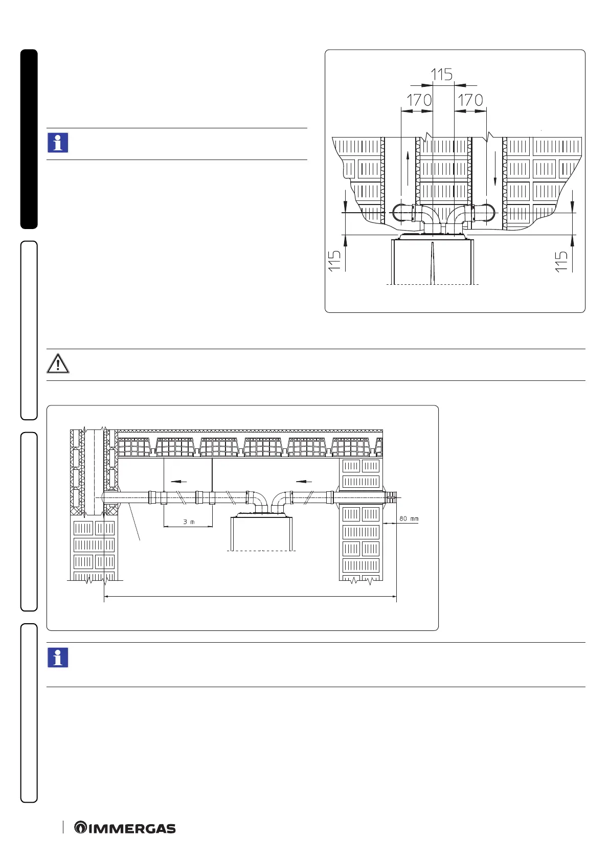
Installation clearances (Fig. 29)
e minimum installation clearance measurements of the Ø
80/80 separator terminal kit have been stated in some limit condi-
tions.
* Conguration C
4
envisages connection to ues working with nat-
ural draught.
For technical data concerning conguration C
4
please
refer to the table in par. 4.3.
C
43
29
Extensions for separator kit Ø 80/80 (L = maximum length)
To aid in the removal of possible condensate forming in the exhaust pipe, tilt the pipes towards the appliance with a minimum
slope of 5% (Fig. 30).
Please note the type of installation C
43
must be done with a natural draught ue.
C
83
C
S
A
L
30
Key (Fig. 30):
A - Intake
C - Minimum slope 5%
S - Exhaust
L - Maximum length
To calculate the length of the ue, simply add, for each component you intend to use, the corresponding value indicated in the
column "Length equivalent to m of pipe" in the table in par. 1.14, and check that the resulting sum is equal to or less than the
maximum length indicated in par. 1.15.
 Loading...


