67
INSTALLER
USERMAINTENANCE TECHNICIAN
TECHNICAL DATA
Pump release.
If aer a long period of inactivity, the circulator is blocked, adjust the screw in the centre of the head in order to manually release the mo-
tor sha.
Take great care during this operation to avoid damage to the motor.
Bypass Adjustment (Parag.1.36).
e appliance leaves the factory with the bypass open.
If necessary, the by-pass can be regulated to system requirements from minimum (by-pass closed) to maximum (by-pass open).
Adjust using a at head screwdriver, turn clockwise and open the by-pass, anticlockwise it is closed.
e bypass ensures minimum circulation of the water in the appliance and its correct operation if the systems are divided into
more than one zone.
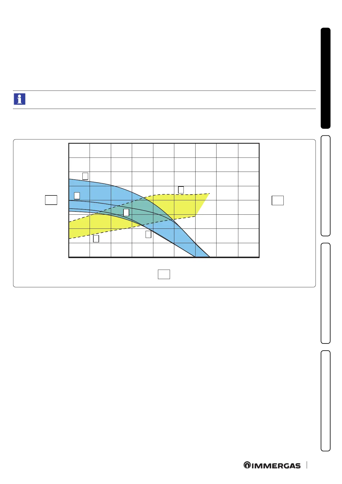
Total head available to the system.
Victrix Tera V2 24 Plus EU
Y1
Y2
2
3
4
6
0
10
20
30
40
50
60
70
0
10
20
30
40
50
60
70
0
200
400
600 800 1000
1200 1400
1600 1800
1
5
49
Key (Fig. 49)
1 = Head available to the system at speed 95% with by-pass closed
2 = Head available to the system at speed 95% with by-pass open
3 = Head available to the system at speed 65% with by-pass closed
4 = Head available to the system at speed 65% with by-pass open
5 = Circulator absorbed power at 95% speed with closed by-pass
6 = Circulator absorbed power at 65% speed with closed by-pass
Area between curves 1 and 3 = Available system head with bypass closed
Area between curves 2 and 4 = Available system head with bypass open
Area between curves 5 and 6 = Circulator absorbed power with bypass
closed
X1 = Flow rate (l/h)
Y1 = Head (kPa)
Y2 = Power absorbed by pump (W)
 Loading...


