9
STZSkW ed 12/07 ZEUS Superior kW
Technical Documentation
Technical Documentation
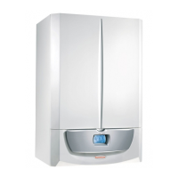
Safety devices and controls.
Adjustable system by-pass (2).
e adjustable system by-pass guarantees water circulation in
the primary circuit (between ow and return) even when high
resistance in the system would not allow circulation.
By-pass is assembled on the ow manifold group (1) and can be
adjusted by acting on a screw to be accessed from underneath
the valve support plate.
System lling valve group (3).
e system lling valve group consists in a ball valve located
between the boiler circuit and the cold domestic water inlet,
which allows the central heating system to be pressurized.
e cock is connected to a lling tting (4) which is connected
to the 3-way valve group.
Absolute pressure switch (5).
Detects the pressure inside the primary circuit.
It is housed in the ow collector unit(1) and is coupled to a
micro switch that prevents burner operating when the pressure
detected is lower than 0.3 bar.
It prevents over-heating of the main heat exchanger.
Automatic vent valve (6).
e vent valve automatically expels any gaseous substances
from the boiler circuit.
e valve is located on the pump ow pipe directly on the
hy draulic group.
3-bar safety valve (7).
e safety valve ensures 3-bar safety pressure not to be ex-
ceeded.
It is inserted on the front of the ow manifold group (1) and
it is secured by a clip.
When triggered, the safety valve releases water from the ow
pipe.
System expansion vessel (8).
e expansion vessel compensates the variations in volume
caused when water is heated, and therefore it changes in
pressure.
e vessel has a 10-litre capacity (7.1 liter useful capacity) and
a 1.0 bar factory set pressure.
It is located above the storage tank and is connected to the
3-way valve group by a copper pipe.
System ow
8
 Loading...