12
STZSkW ed 12/07 ZEUS Superior kW
Technical DocumentationTechnical Documentation
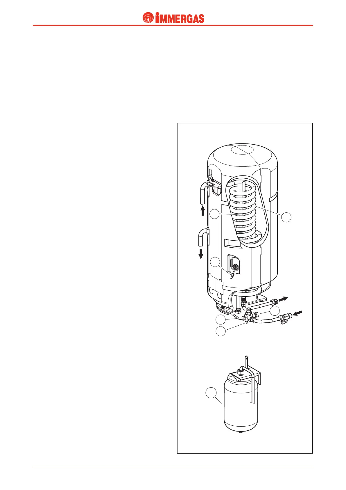
Storage tank.
It is a storage tank with coil and total capacity of 60 litres (useful
54 litres) built entirely out of stainless steel and is completely
insulated with self-extinguishing polystyrene.
It is made up of an external liner enclosed in the lower part by
a ange xed using12 screws.
A stainless steel pipe (4) is located inside the tank, shaped like
a con centric spiral (coil) which develops through the lower
part of the boiler. e heat exchange between the hot water
in the primary circuit and the water in the storage tank takes
place through the coil surface.
is keeps the water in the storage tank at a constant tem-
perature and guarantees instantaneous production of DHW
whenever water is drawn.
If necessary, the coil can be removed from the storage tank after
the lower inspection ange has been removed.
Storage tank integrity and function are guaranteed by the
following devices:
Anode (1).
e anode is inserted in the storage tank and protects it against
corrosive actions of galvanic currents.
It is screwed onto the lower ange.
Polyphosphate dispenser (optional).
e polyphosphate dispenser prevents the formation of scale
on the coil surface. e kit is assembled on domestic cold
water inlet pipe.
Recirculation kit (option).
Recirculation kit allows for DHW recirculation system pipes
to be connected.
It consists in a pipe, which is inserted in the boiler after the
anode and relative plug have been removed.
When the kit is installed, the anode is screwed onto the end
of the pipe.
An additional kit is available (option) which includes a pump
for DHW recirculation system.
e kit is not protruding outside the boiler clearance while the
pump slightly extends beyond the plastic grille at the bottom
of the appliance.
DHW NTC probe (B2) (9).
e DHW probe allows integrated P.C.B. to read temperature
of water inside the storage tank.
It is secured to the external wall of the water tank and it is
inserted in an sample point.
Safety valve group (13).
e safety valve group is located in the lower part of the storage
tank near the domestic cold water inlet.
As well as an 8-bar valve (10) which prevents the storage tank
safety pressure from being exceeded, it includes:
- a lter, a 12 l/min ow limiter (24 kW version and 28 kW
version) and14 l/min (32 kW), a storage tank draining valve
with hose union (12) and a one-way valve (see hydraulic cir-
cuit paragraph, detail “5”) in order to ensure that increased
pressure DHW does return toward water mains supply.
11
Domestic hot water expansion vessel (11).
DHW expansion vessel compensates for any variations in
volume caused by water in the storage tank.
It is connected to the safety valve group and has a 2-litre ca-
pacity with a 3.5-bar factory set pressure.
Coil ow
Cold
water
inlet
Hot
water
outlet
Coil return