20
STZSkW ed 12/07 ZEUS Superior kW
Technical DocumentationTechnical Documentation
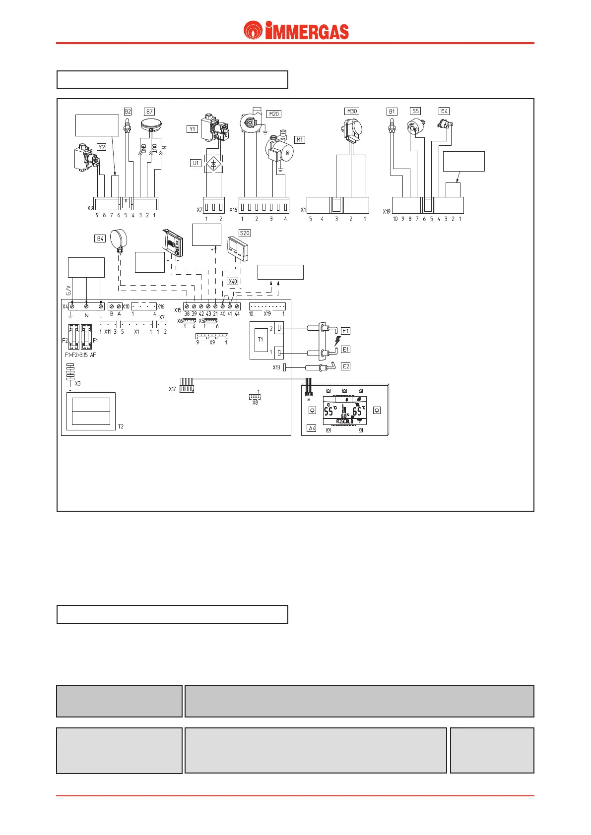
Electric circuit.
e electrical circuit on ZEUS Superior kW is a total slave to
the inte grated electronic microprocessor P.C.B. which controls
all boiler function.
Control and safety devices run partly on 230 V AC power
supply voltage and partly on low voltage.
Key:
A4 - Display board
B1 - Flow probe
B2 - D.H.W. probe
B4 - External probe (option)
B7 - Flue ow meter
CAR - Comando Amico Remoto remote control (option)
CZ - Zone control units (option)
E1 - Ignition electrodes
E2 - Detection electrodes
E4 - Safety thermostat
F1 - Line fuse
F2 - Neutral fuse
M1 - Pump
M20 - Fan
M30 - Motorized three-way valve
S5 - System pressure switch
S20 - Room thermostat (option)
Super CAR - Super CAR remote control (option)
T1 - Ignition transformer
T2 - Boiler card transformer
230 V AC circuit.
Safety devices and controls
U1 - Rectier inside the gas valve connector
(only present on Honeywell valves)
X40 - Room thermostat jumper
Y1 - Gas valve
Y2 - Gas valve modulation coil
DPNNPO
EPNFTUJDIPU
XBUFS
IFBUJOH
4503"(&5"/,
$0/'*(63"5*0/
+6.1&3
#MBDL
#MBDL
#MBDL
#MVF
(SFFO
(SFFO
0SBOHF
3FE
#SPXO
#MVF
#SPXO
#MVF
(SFZ
#MBDL
#MBDL
8IJUF
3FE
#MBDL
#MBDL
3FE
3FE
8IJUF
8IJUF
#MBDL
4&"-&%
$0/'*(63"5*0/
+6.1&3
7"$);
108&34611-:
#MVF
#SPXO
13*."3:
4&$0/%"3:
*.(#64
$0//&$5*0/
;0/&
#0"3%
015*0/"-
$"303
461&3$"3
Detects whether the burner is it (enveloped by ame).
Connected to the integrated P.C.B.
Detection electrode
(E2)
Disconnects power supply to the circuit when the input current
exceeds 3.15 A.
Assembled on the integrated P.C.B.
Line fuse (F1)
Neutral fuse (F2)
Fuse
3.15 AF 250 V