14
STZSkW ed 12/07 ZEUS Superior kW
Technical DocumentationTechnical Documentation
Gas adjustments.
In order to adjust maximum and minimum gas pressure it is
necessary to act on the valve. Any adjustments must comply
with the values indicated in the charts regarding each boiler
for the type of used gas (see the technical data sheets).
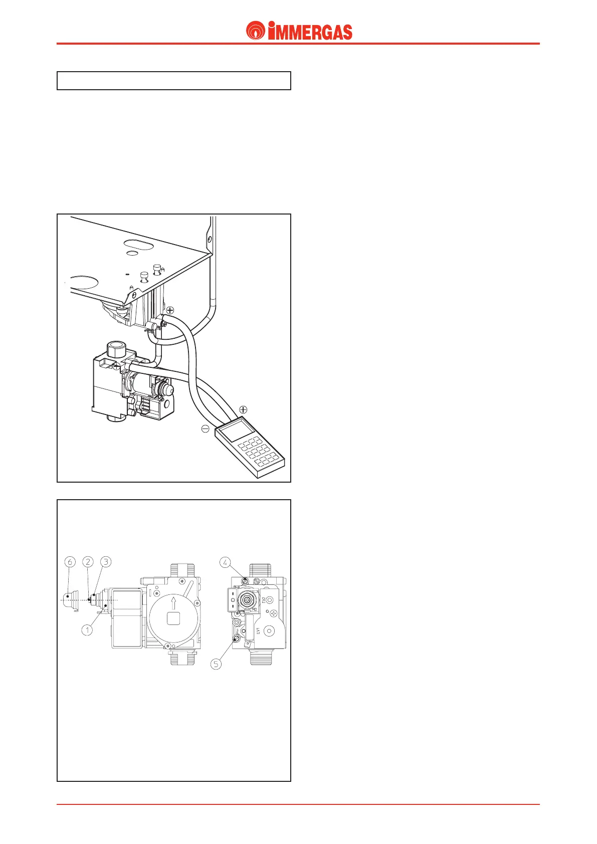
Use a dierential gauge to carry out any measurements. Con-
nect the positive pressure point to the gas valve outlet (4) and
to the positive pressure point present in the ue ow meter
support found under the sealed chamber (see gure).
Key:
1 - Coil
2 - Minimum power regulation screws
3 - Maximum power regulation nut
4 - Gas valve outlet pressure socket
5 - Gas valve inlet pressure socket
6 - Protective hood
SIT 845 valve
SIT 845 gas valve.
Maximum pressure adjustment.
Set the DHW temperature selector to maximum output and
then open a tap.
Turn the brass nut (3) clockwise to increase the burner pressure
and anti-clockwise to decrease.
Minimum pressure adjustment.
(First, adjust maximum pressure and then minimum pressu-
re). Disconnect power supply from the modulation coil; then
turn the screw (2) clockwise to increase the burner pressure
and anti-clockwise to decrease it.
Gas transformation.
e adaptation to the type of gas dierent to that for which
the boilers are prepared as per standard is performed using the
relevant kit (natural gas or LPG).
e transformation consists in the replacement of the burner
nozzles and modication of the "P56" parameter, which can
be programmed on the integrated circuit board (see integrated
P.C.B. programming).
e domestic hot water minimum and maximum pressures
are therefore adjusted on the gas valve in the way described
above.
e adjustments of the maximum and minimum powers in the
heating phase can be set through the parameters (see integrated
P.C.B. functioning).
e ignition pressure of the burner is not adjusted as the
particular functioning of the boarddoes not require this type
of calibration (see integrated P.C.B. functioning).