6
STZSkW ed 12/07 ZEUS Superior kW
Technical DocumentationTechnical Documentation
Primary circuit (boiler circuit).
e primary circuit (and its relative control and safety devices)
is enabled every time there is a heating or DHW request.
Operation.
e heat in combustion exhaust is transferred by copper ns
to the water-gas exchanger (8). e water-gas exchanger then
transfers such heat to the water circulating inside it thanks to
the boiler pump (16).
e water is then pushed directly into the system or it can be
diverted to the storage tank coil (2).
is depends on the position of the electric 3-way valve (20)
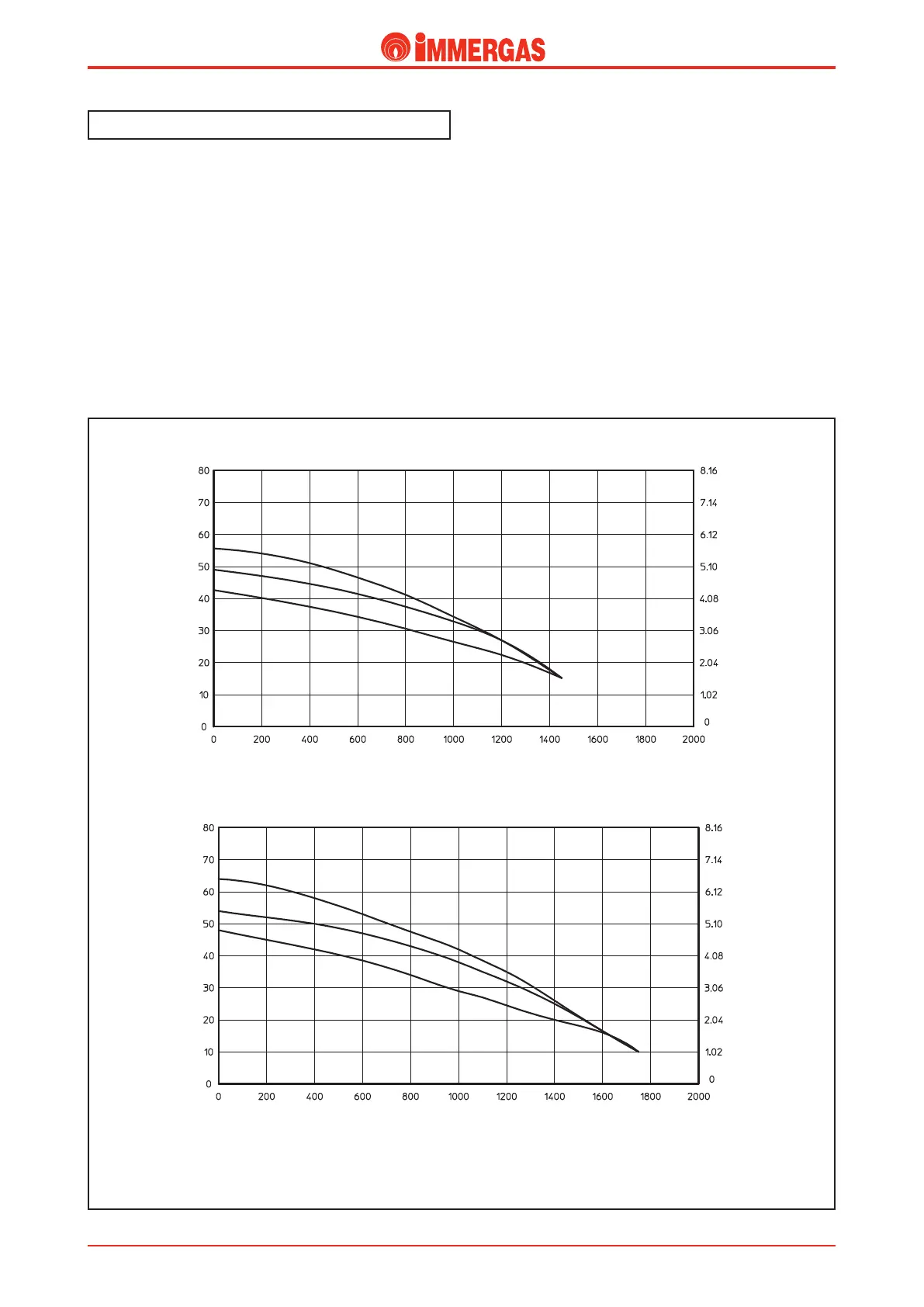
Head (kPa)
Flow rate Litres/h
A
A = Head available to the system at maximum speed with by-pass excluded (adjusting screw completely tightened)
B = Head available to the system at maximum speed (screw tightened by 1.5 revulution with respect to the completely loose adjusting screw)
C = Head available to the system at maximum speed with by-pass open (adjusting screw completely loose)
Head (m H
2
O)
ZEUS Superior 24 kW
Head (kPa)
Flow rate Litres/h
Head (m H
2
O)
ZEUS Superior 28 kW
B
C
A
B
C
which, according to the type of request, either allows water to
ow through the central heating ow system (M) and return
(R) pipes or diverts the water towards the coil (2).
Flow rate - head graph.
e shape of the curve representing the ow rate-head ratio
will depend on how the system by-pass is adjusted; thus, the
position of the by-pass will provide more or less head to the
system. e graph below illustrates the characteristic curves
according to the by-pass adjustment.