5
STZSkW ed 12/07 ZEUS Superior kW
Technical Documentation
Technical Documentation
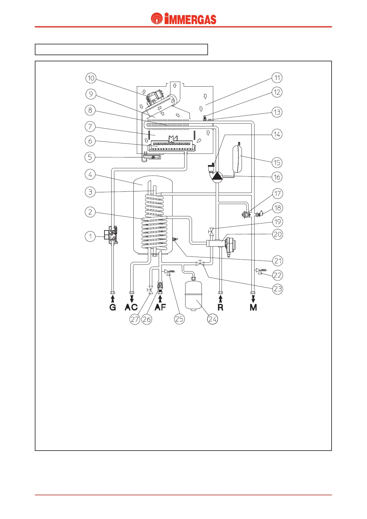
e hot water used for heating and DHW is produced by a pri-
mary and secondary (DHW) circuit according to demand.
ZEUS Superior kW hydraulic layout.
18 - System pressure switch
19 - Draining valve
20 - Motorized 3 - way valve
21 - Flow probe
22 - 3 bar safety valve
23 - Filling valve
24 - D.H.W. expansion vessel
25 - 8 bar safety valve
26 - Cold inlet one - way valve
27 - Storage tank drain valve
G - Gas supply
AC - D.H.W. ow
AF - Domestic hot water inlet
R - C.H. return
M - C.H. ow
Key
1 - Gas valve
2 - Stainless steel storage tank coil
3 - Magnesium anode
4 - Stainless steel storage tank
5 - Fume ow meter
6 - Burner
7 - Combustion chamber
8 - Primary heat exchanger
9 - Flue hood
10 - Fan
11 - Sealed chamber
12 - Flow probe
13 - Safety thermostat
14 - Automatic vent valve
15 - System expansion vessel
16 - Boiler pump
17 - Adjustable by-pass