0:2-wire control 1, comply the enable with the direction.
This mode is widely used. It determines the rotation
direction by the defined FWD and REV terminals
command.
1:2-wire control 2;Separate the enable from the
direction. FWD defined by this mode is the enabling
ones. The direction depends on the state of the defined
REV.
2:3-wire control 1; Sin is the enabling terminal in this
mode, and the running command is caused by FWD and
the direction is controlled by REV. Sin is natural closed.
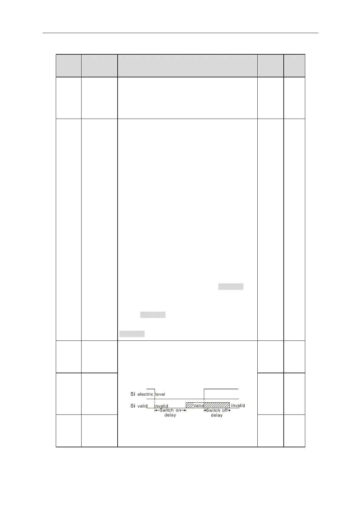
3:3-wire control 2; Sin is the enabling terminal on this
mode, if set Si (i=1~5) to 3, when K is switched on, the
control of FWD and REV is valid; when K is switched off,
the control of FWD and REV is invalid. The inverter
stops.
Note: for the 2-wire running mode, when FWD/REV
terminal is valid, the inverter stop because of the
stopping command from other sources, even the control
terminal FWD/REV keeps valid; the inverter won’t work
when the stopping command is canceled. Only when
FWD/REV is relaunched, the inverter can start again.