iDrive2 inverters Function Parameters
50
Detailed instruction of parameters
Setting range of P08.25:P08.26~65535
Setting range of P08.26:0~P08.25
Pre-set running time of the inverter. When the
accumulative running time reaches the set time, the
multi-function digital output terminals will output the
signal of “running time arrival”.
The time of the fault reset: The fault reset time can be
set by this function. If the reset time exceeds this set
value, the inverter will stop for the fault and wait to be
repaired.
The interval time of the fault reset: The interval between
the time when the fault occurs and the time when the
reset action occurs.
Setting range of P08.28:0~10
Setting range of P08.29:0.1~3600.0s
Interval time
of automatic
fault reset
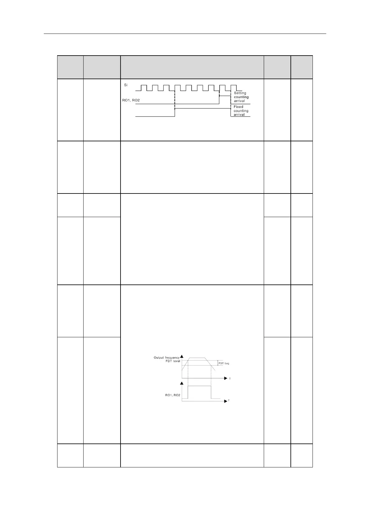
FDT
electrical
level
detection
value
When the output frequency exceeds the corresponding
frequency of FDT level, the multi-function digital output
terminals will output the signal of “frequency level detect
FDT” until the output frequency decreases to a value
lower than (FDT electrical level—FDT retention
detection value) the corresponding frequency, the signal
is invalid. Below is the waveform diagram:
Setting range of P08.32: 0.00Hz~P00.03(the Max.
frequency)
Setting range of P08.33: 0.0~100.0%(FDT electrical
level)
FDT
retention
detection
value
When the output frequency is below or above the range
of the set frequency, the multi-function digital output