iDrive2 inverters Function Parameters
51
Detailed instruction of parameters
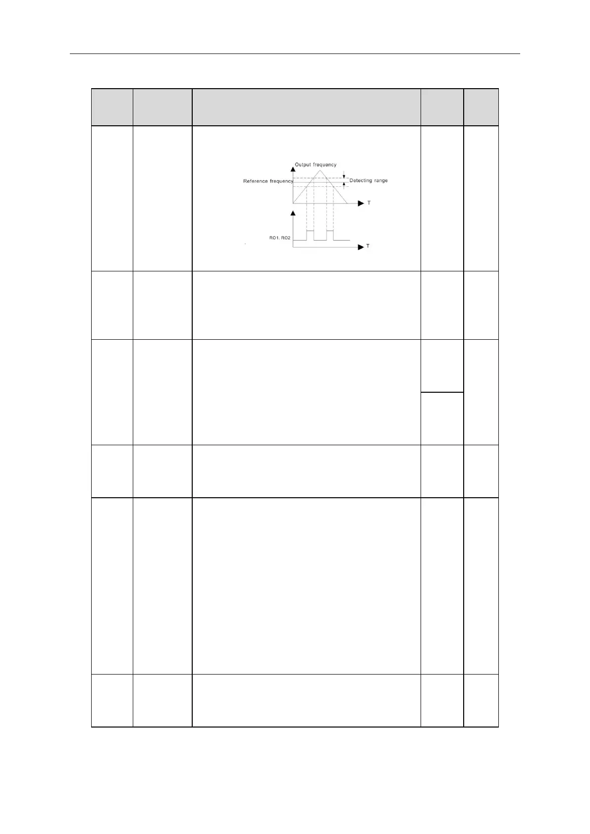
terminal will output the signal of “frequency arrival”, see
the diagram below for detailed information:
The setting range:0.00Hz~P00.03(the Max. frequency)
Used to control the internal braking resistor.
0:Disabled
1:Enabled
Note: Only applied to internal braking resistor.
Energy
Braking
threshold
voltage
After setting the original bus voltage, adjust this
parameter to brake the load appropriately. The factory
value changes with voltage level.
The setting range:200.0~2000.0V
0: Thermal fan switching control.
LED ones: PWM mode selection
0: PWM mode 1, Three-phase modulation and
two-phase modulation
1: PWM mode 2, Three-phase modulation
LED tens: low-speed carrier frequency limit
0: low-speed carrier frequency limit mode 1; when the
carrier frequency exceeds 1k at low speed, limit to 1k.
1: low-speed carrier frequency limit mode 2; when the
carrier frequency exceeds 2k at low speed, limit to 2k.
2: No limit for the carrier frequency at low speed
Over
commission
selection