iDrive2 inverters Function Parameters
56
Detailed instruction of parameters
Output upper
limit of PID
These parameters are used to set the upper and lower
limit of the PID adjustor output.
100.0 % corresponds to Max. Frequency
Setting range of P09.09: P09.10~100.0%
Setting range of P09.10: -100.0%~P09.09
Output lower
limit of PID
Feedback
offline
detection
value
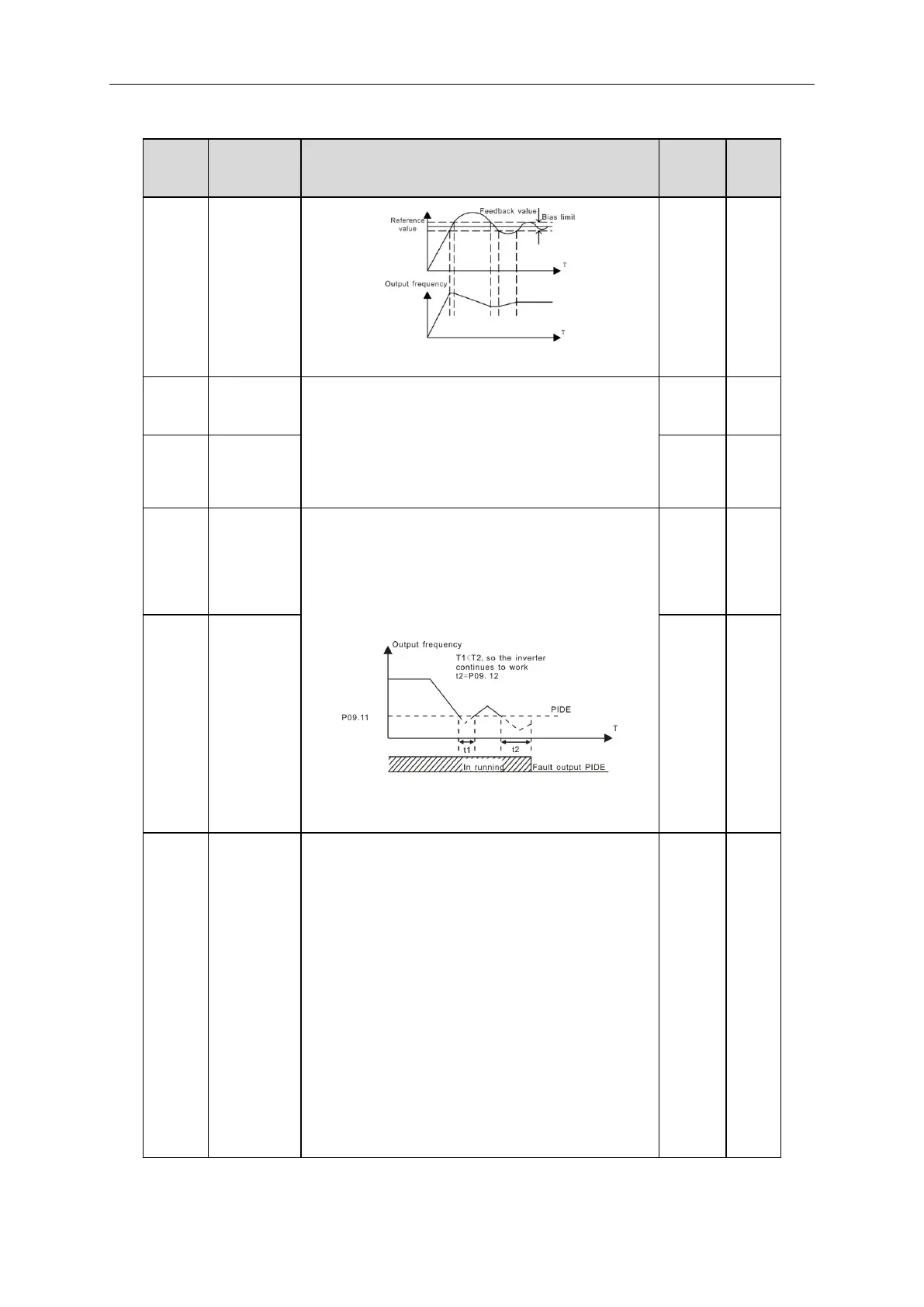
Set the PID feedback offline detection value, when the
detection value is smaller than or equal to the feedback
offline detection value, and the lasting time exceeds the
set value in P09.12, the inverter will report “PID
feedback offline fault” and the keypad will display PIDE.
Setting range of P09.11: 0.0~100.0%
Setting range of P09.12: 0.0~3600.0s
Feedback
offline
detection
time
LED ones:
0: Keep on integral adjustment when the frequency
achieves the upper and low limit; the integration shows
the change between the reference and the feedback
unless it reaches the internal integral limit. When the
trend between the reference and the feedback changes,
it needs more time to offset the impact of continuous
working and the integration will change with the trend.
1: Stop integral adjustment when the frequency reaches
the upper and low limit. If the integration keeps stable,
and the trend between the reference and the feedback
changes, the integration will change with the trend