LED tens:
0: The same with the setting direction; if the output of
PID adjustment is different from the current running
direction, the internal will output 0 forcedly.
1:Opposite to the setting direction
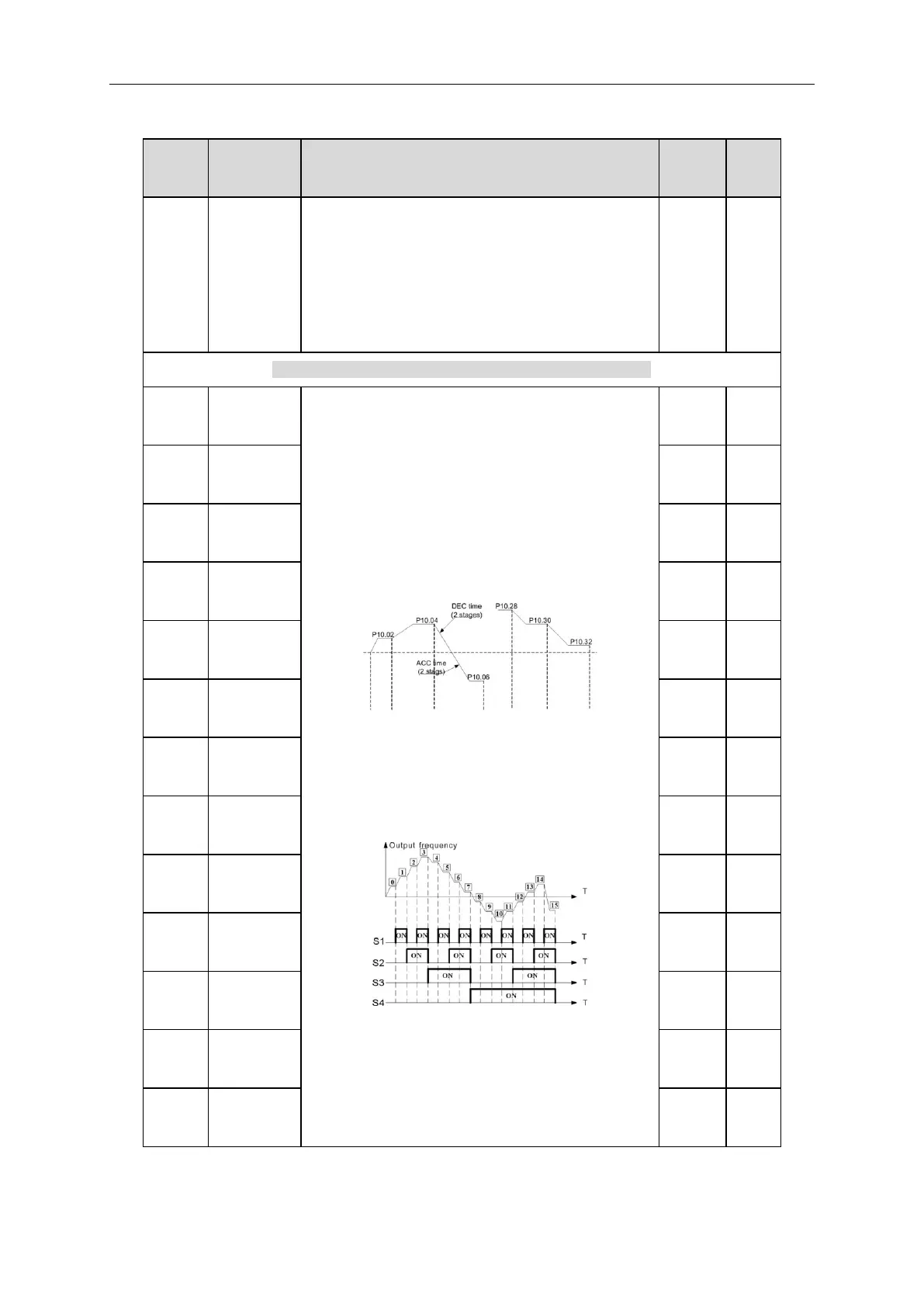
When selecting simple PLC running, set P10.02~P10.33
to define the running frequency and direction of all
stages.
Note: The symbol of multi-stage determines the running
direction of simple PLC. The negative value means
reverse rotation.
Multi-stage speeds are in the range of --f
max
~f
max
and it
can be
IMO XKL series inverters can set 16 stages speed,
selected by the combination of multi-stage terminals
1~4, corresponding to the speed 0 to speed 15.
When S1=S2=S3=S4=OFF, the frequency input
reference is selected via P00.06 or P00.07. When all
S1=S2=S3=S4 terminals aren’t off, it runs at multi-stage
which takes precedence of keypad, analog value,
high-speed pulse, PLC, communication frequency input.