iDrive2 inverters Communication protocol
80
R/W characteristics means the function is with read and write characteristics. For example, “communication
control command” is writing chrematistics and control the inverter with writing command (06H). R characteristic
can only read other than write and W characteristic can only write other than read.
Note: when operate on the inverter with the table above, it is necessary to enable some parameters. For example,
the operation of running and stopping, it is necessary to set P00.01 to communication running command channel
and set P00.02 to MODBUS communication channel. And when operate on “PID reference”, it is necessary to set
P09.00 to “MODBUS communication setting”.
The encoding rules for device codes (corresponds to identifying code 2103H of the inverter)
Note: the code is consisted of 16 bit which is high 8 bits and low 8 bits. High 8 bits mean the motor type series
and low 8 bits mean the derived motor types of the series. For example, 0110H means IMO XKL vector inverters.
7.3.5 Fieldbus ratio values
The communication data is expressed by hex in actual application and there is no radix point in hex. For example,
50.12Hz can not be expressed by hex so 50.12 can be magnified by 100 times into 5012, so hex 1394H can be
used to express 50.12.
A non-integer can be timed by a multiple to get an integer and the integer can be called fieldbus ratio values.
The fieldbus ratio values are refered to the radix point of the setting range or default value in the function
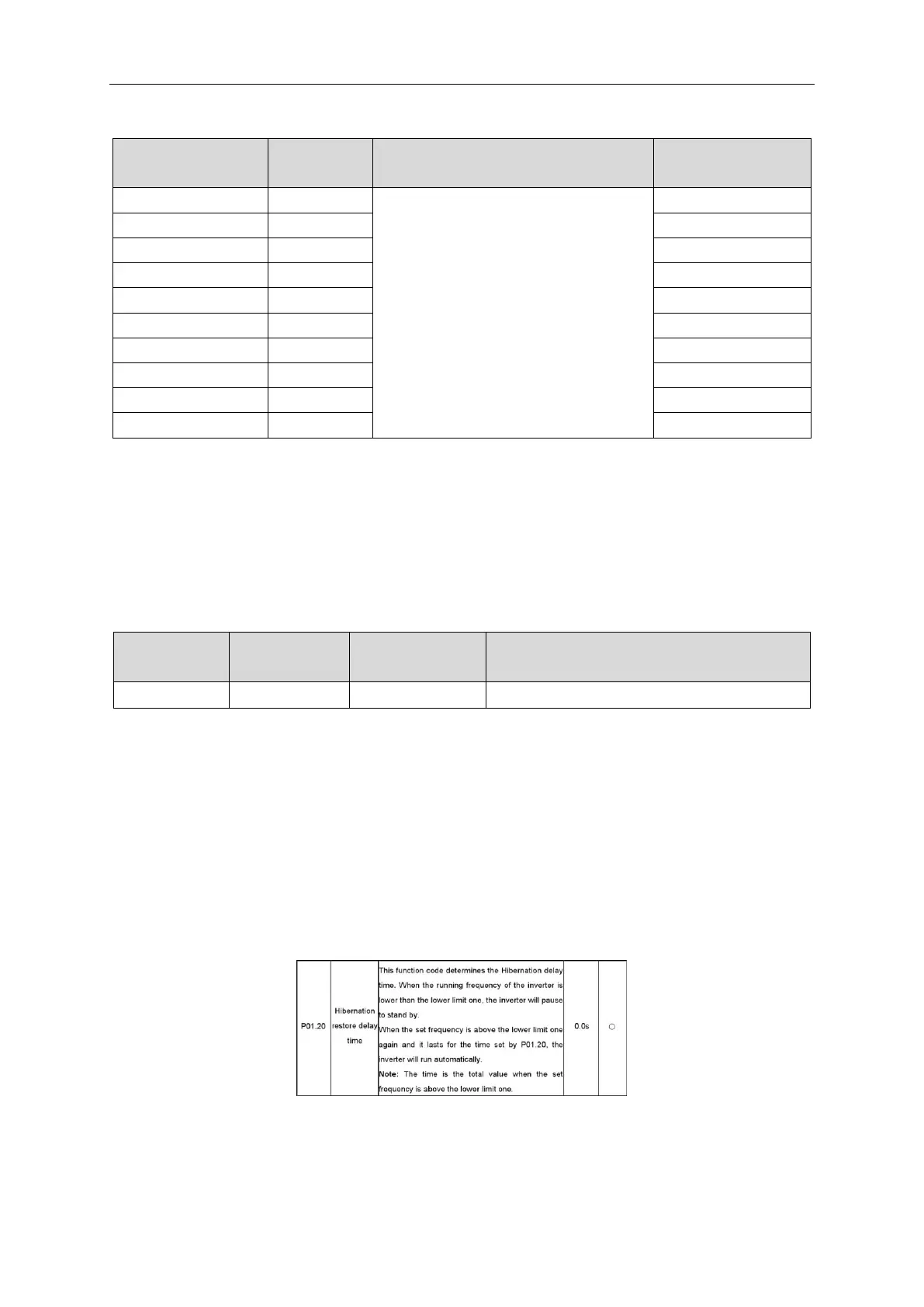
parameter list. If there are figures behind the radix point (n=1), then the fieldbus ratio value m is
. Take the table
as the example:
If there is one figure behind the radix point in the setting range or the default value, then the fieldbus ratio value is
10. If the data received by the upper monitor is 50, then the “hibernation restore delay time” is 5.0 (5.0=50÷10).