www.impro.net Impro Biometric Reader – Installation Manual Page 7 of 25
IBR Hardware installation
Mount and wire the IBR
Follow the steps shown on the Quick Start Guide (PLT-04644), included in the IBR’s carton.
Update the site plan
Apply the spare fixed address label (for each reader) to the site plan to indicate its physical location.
You will need this plan when configuring the Access Portal software.
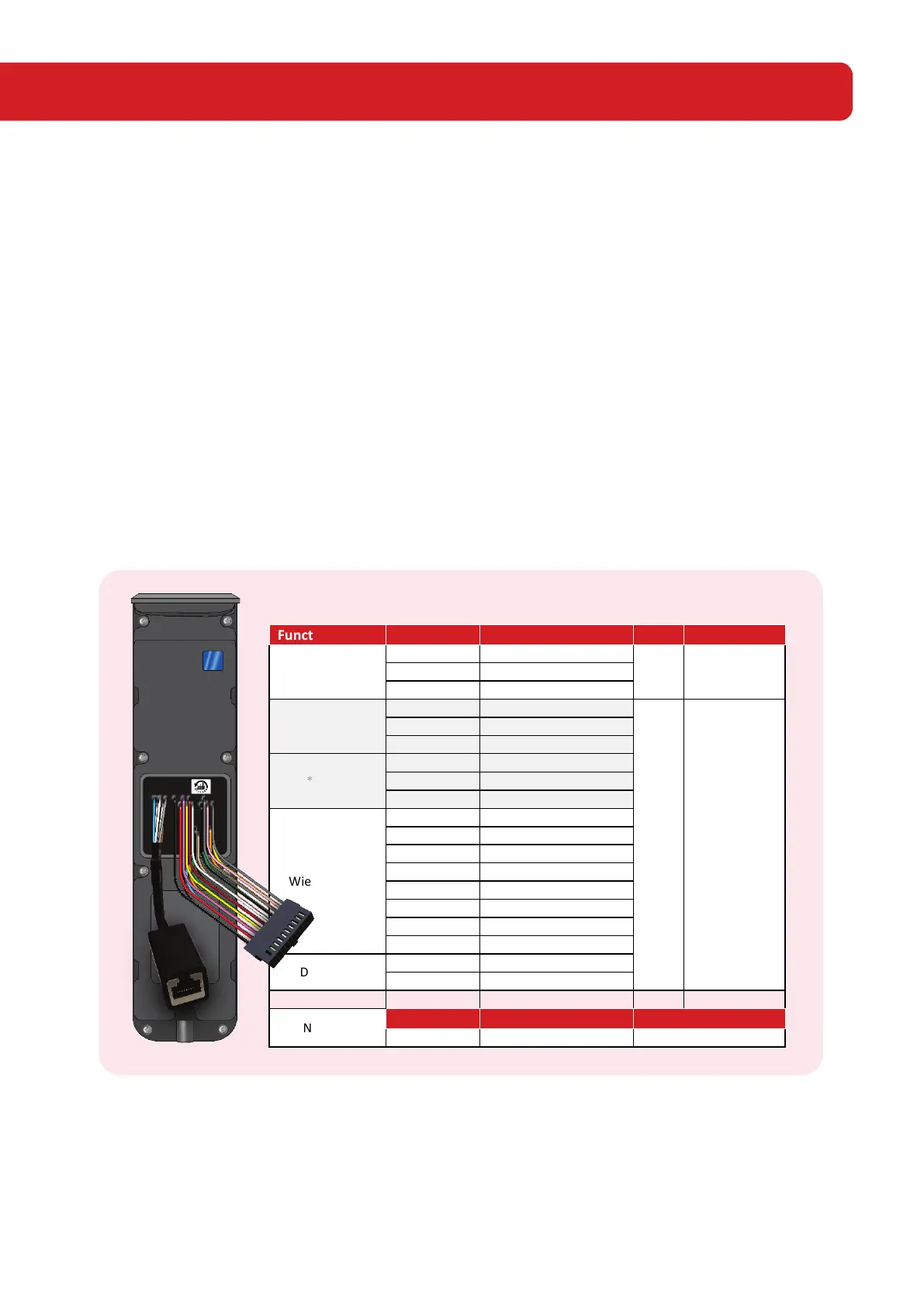
System Connections
Wiring Colour Codes
This list is also duplicated on the PLT-04744 package insert for your convenience
Note:
Do NOT cut the Ethernet cable.
Cut off the pigtail connector (used in the testing stage at the factory). Cut the wires close to the connector and only
strip the wires needed for the installation.
CAUTION:
Incorrect wiring may cause permanent damage to the reader.
RS-485
OSDP
22 1000 m
*Relay
22 150 m
*Inputs
Wiegand Port
DC Power
Network
*The greyed connections are reserved for future use.