INFOSEC UPS SYSTEM – 15, rue du Moulin – 44880 Sautron – France – www.infosec-ups.com
hotline : +33 (0)2 40 76 15 82 – fax : +33(0)2 40 94 29 51 – hotline@infosec.fr – 07 19 AA 59 205 03
it always shows as output voltage.
it shows the internal measurement value of the
output A voltage, and you can calibrate it by pressing or
according to the measurement from an external voltage meter.
The calibration result will be effective by pressing . The
calibration range is limited within +/-9V. This function is normally
used for parallel operation.
it always shows as output voltage*.
it shows the internal measurement value of the
output B voltage, and you can calibrate it by pressing or
according to the measurement from an external voltage meter.
The calibration result will be effective by pressing . The
calibration range is limited within +/-9V. This function is normally
used for parallel operation.
*It will display number 1 under to represent the output B
voltage.
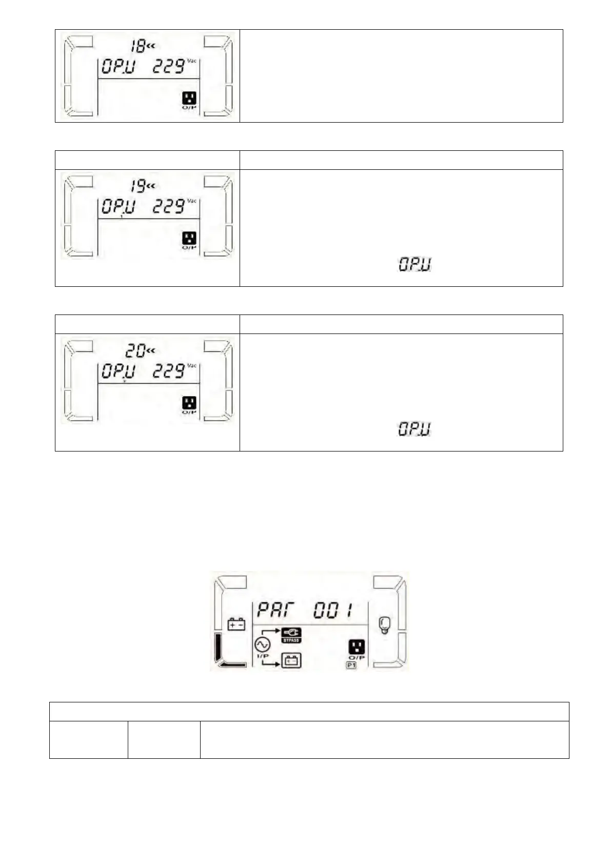
it always shows as output voltage.
it shows the internal measurement value of the
output C voltage, and you can calibrate it by pressing or
according to the measurement from an external voltage meter.
The calibration result will be effective by pressing . The
calibration range is limited within +/-9V. This function is normally
used for parallel operation.
*It will display number 2 under to represent the output C
voltage.
Following table shows LCD display for operating modes and status.
(1) If the UPS is in normal operation, it will show seven screens one by one, which represents 3 phase input
voltages (An, bn, Cn), 3 line input voltages (Ab, bC, CA) and frequency in turns.
(2) If parallel UPS systems are successfully set up, it will show one more screen with “” in parameter 2
and assigned number in parameter 3 as below parallel screen diagram. The master UPS will be default
assigned as “” and slave UPSs will be assigned as either “002” or “003”. The assigned numbers may be
changed dynamically in the operation;
When UPS is powered on, it will enter into this mode for a few seconds as
initializing the CPU and system.
 Loading...