20
3.6 WARNINGS
When a warning occurs, the alarm indicator will flash
and the display will alternate between the current
message and the warning message. If multiple
warnings exist, the message
SCROLL FOR WARN
will be substituted for the warning messages. The up
and down arrows can be used to obtain the
warnings
A warning needs to be reset by an operator. The
warning will clear when the SET button is pressed
once. The following is a list of the warning
messages.
1) CHG SEPR ELEMENT
This warning will occur if the pressure on the
Separator is 12 psig (.8 bar) greater than the
pressure at the Package discharge and the unit is
fully loaded.
2) HIGH AIREND TEMP
This will occur if the Airend Discharge Temperature
(2ATT) exceeds 221°F (105°C).
3) HIGH AIR PRESS
This will occur if the unit is connected to an ISC
(sequencer), and the line pressure exceeds the max.
offline pressure for 3 seconds.
4) T2 SENSOR FAILURE
This will occur when the Low Ambient Option is
turned on and either the low ambient sensor is not
installed or is broken.
3.5 SET POINT PROCEDURE
This procedure allows the customer to modify 14
variables in the controller logic.
At this time, press the SET button to enter the
setpoint routine. The SET OFFLINE AIR
PRESSURE indicator will light and the display will
show:
XXXX PSI
OFFLINE AIR PRESSURE is the first set point and
XXXX stands for the value of the set point. Press the
SET button to select the set point to be adjusted.
Press the up or down arrow buttons to raise or lower
the set point value. Press the SET button to move to
the next set point. If the set point value has been
adjusted, press the SET button to enter the new
value. The display will flash to acknowledge.The next
set point will then be displayed. If the value of the set
point was not changed, pressing the SET button will
only step to the next set point. When the SELECT
OPTIONS set point is entered, the SELECT
OPTIONS indicator will light, and the setpoints for
options Auto Start/Stop or Remote Start/Stop will
only be accessible and displayed if the option
module is installed in the unit. The Power Outage
Restart setpoints will only be accessible and
displayed if the combination Auto/Remote
Start/Stop/Power Outage Restart option module is
installed in the unit. The set point routine can be
exited by pressing the DISPLAY/SELECT button or
exit will be automatic after 30 sec.
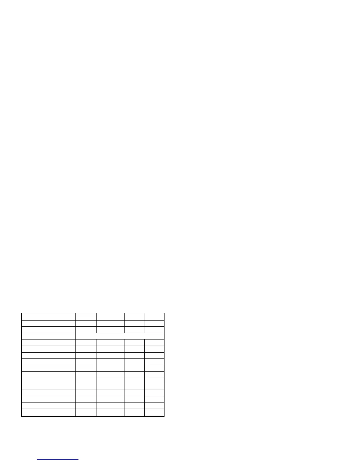
The following is a list of the set points. Also included
are maximum and minimum limits, step size, and
units of measure.
MIN MAX STEP UNIT
OFFLINE PRESSURE 75 RATED + 3 1 PSI
ONLINE PRESSURE 65 OFFLINE - 10 1 PSI
CONTROL MODE MOD/ACS - MODULATION - ON/OFF LINE
DISPLAY TIME 10 600 10 SEC
AUTO RESTART OFF ON --- ---
AUTO RESTART TIME 2 60 1 MIN
SEQUENCER OFF ON --- ---
REMOTE START/STOP * OFF ON --- ---
POWER OUT/RESTART* OFF ON --- ---
POWER OUT RESTART 10 120 1 SEC
TIME *
DELAY LOAD TIME 0 60 1 SEC
LEAD/LAG** --- --- --- ---
LAG OFFSET 0 45 1 PSI
LOW AMBIENT OFF ON --- ---
*Optional
** The lead/lag feature allows the customer to choose
one compressor as the “lead” compressor and any
others as the “lag” compressor (simulates the mode of a
sequencer). The lag compressor’s on-line and off-line
pressures are determined by subtracting the lag offset
set-point from the on-line and off-line pressure set-
points of the lead compressor.
 Loading...