5.11 LONG TERM STORAGE
General
The factory, upon special request, prepares compressor
units for long term storage. In such cases, a special
bulletin is supplied for storage and start-up procedures.
The bulletin provides special procedures for rotation and
lubrication of compressors during storage.
Before actual start-up of the compressor, the unit must
be drained of coolant containing vapor space inhibitors.
Procedure for long term storage start-up is covered in the
special bulletin APDD 339.
5.12 COOLANT/LUBRICANT CHANGEOUT
Ingersoll-Rand does not recommend changeout of
coolant/lubricants, however, if a coolant/lubricant
change cannot be avoided, procedure APDD 106E-87
should be obtained from your Ingersoll-Rand
representative.
5.13 INTELLISYS REMOVAL
Ensure that the compressor is isolated from the
compressed air system by closing the isolation
valve and venting pressure from the drip leg.
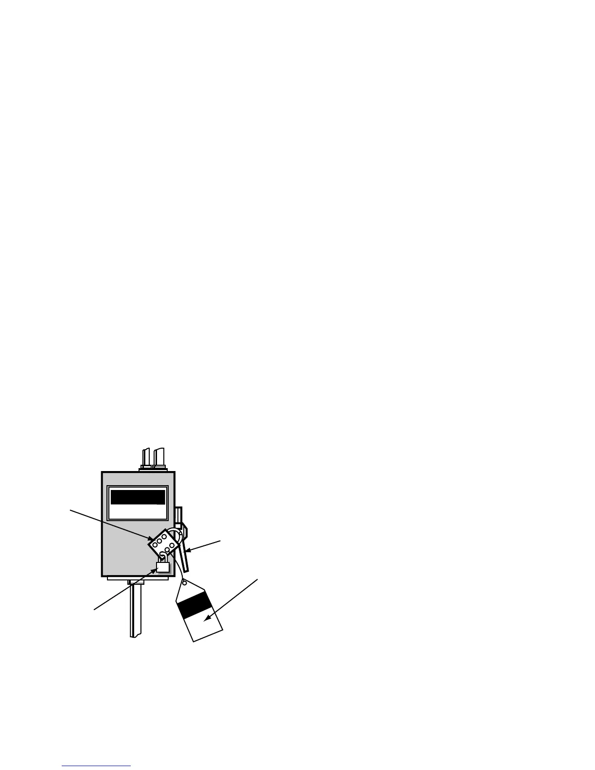
Ensure that the main power disconnect switch is
locked open and tagged (See Figure 5.13-1).
FIGURE 5.13-1 MAIN DISCONNECT
LOCKED AND TAGGED
Follow these precautions to minimize damage from
static electricity. Static can cause severe damage to
microcircuits.
1) Make the least possible movement to avoid build-
ing up static electricity from your clothing or tools.
2) Discharge potential static electricity by touching
(grounding) yourself to the starter box.
3) Handle circuit boards only by their edges.
4) Do not place the controller or power supply
assembly on any metal surface.
5) Leave the replacement parts in their protective
bags until ready for installation.
Tools:
Screwdriver Size #1, flathead
3/8 inch hex driver
Before removing any components, open the starter box
door and check all wiring for tightness. A loose wire or
bad connection may be the cause of problems.
Controller Removal:
1) Open the starter box door.
2) Remove the five electrical plug-in connectors from
the top of the controller.
3) Remove (2) mounting rails that attach the
Intellisys® Controller at the side of the control box.
4) Remove the controller. Remove any option
modules which must be installed in the new
controller.
38
 Loading...