"do1", "dev_node": "/sys/class/gpio/gpio323" }, {
"do_name":
"do2", "dev
_node": "/sys/class/gpio/gpio453" }, { "do_name":
"do3", "dev_node": "/sys/class/gpio/gpio465" },
{ "do_name":
"
do4", "dev_node": "/sys/class/gpio/gpio461" } ] } } }}
7.1 IO Programming Guide
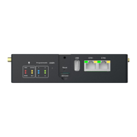
Currently, there are a total of 8 IO interfaces on the device: for example, there
are 4 input pins from DI1 to DI4 on the device panel; DO1~DO4 are 4 output pins.
According to the device description file /tmp/ieos/etc/system_info.json, the IO
device nodes are:
When you need to programming IO interface, direct manipulation background device
nodes below the value value (sys/class/gpio/gpioxxx/value)
Case study:
 Loading...