14 Control panel and peripherals
Anti-intrusion control panels
2-1-3
LED activity
The LEDs on the control panel motherboard (refer to Table 2-6: Mother board - description of
parts, J) can providing useful information regarding the proper operating capacity of the
control panel and I-BUS. Specifically:
GREEN POWER LED
Green LED ON solid indicates the presence of electrical power. If ON solid it indicates that the
control panel is operating properly. LED OFF or blinking indicates power failure or the presence
of trouble. The control panel will continue to operate until the battery disconnection threshold
for deep discharge is reached (9.5V).
BLUE EXE LED
During normal operation of the control panel, the blue LED will blink rapidly. On exiting the
installer menu at the end of a programming session via PC, during reset of factory default
settings and during reprogramming operations on the control panel and peripheral firmware,
this LED may be either ON solid or OFF for the entire duration of the operation in progress.
However, once the operation has been completed it should start blinking as previously
described.
If the LED is ON or OFF permanently in situations other than those previously described, it
indicates that all the functions of the control panel are blocked.
YELLOW BUS LED
During normal operation of the control panel and if the system has at least one peripheral on
the I-BUS, the yellow LED will flicker. On exiting the installer menu at the end of a
programming session via PC, during reset of factory default settings and during
reprogramming operations on the control panel and peripheral firmware, this LED may be
either ON solid or OFF for the entire duration of the operation in progress. However, once the
operation has been completed it should start blinking as previously described.
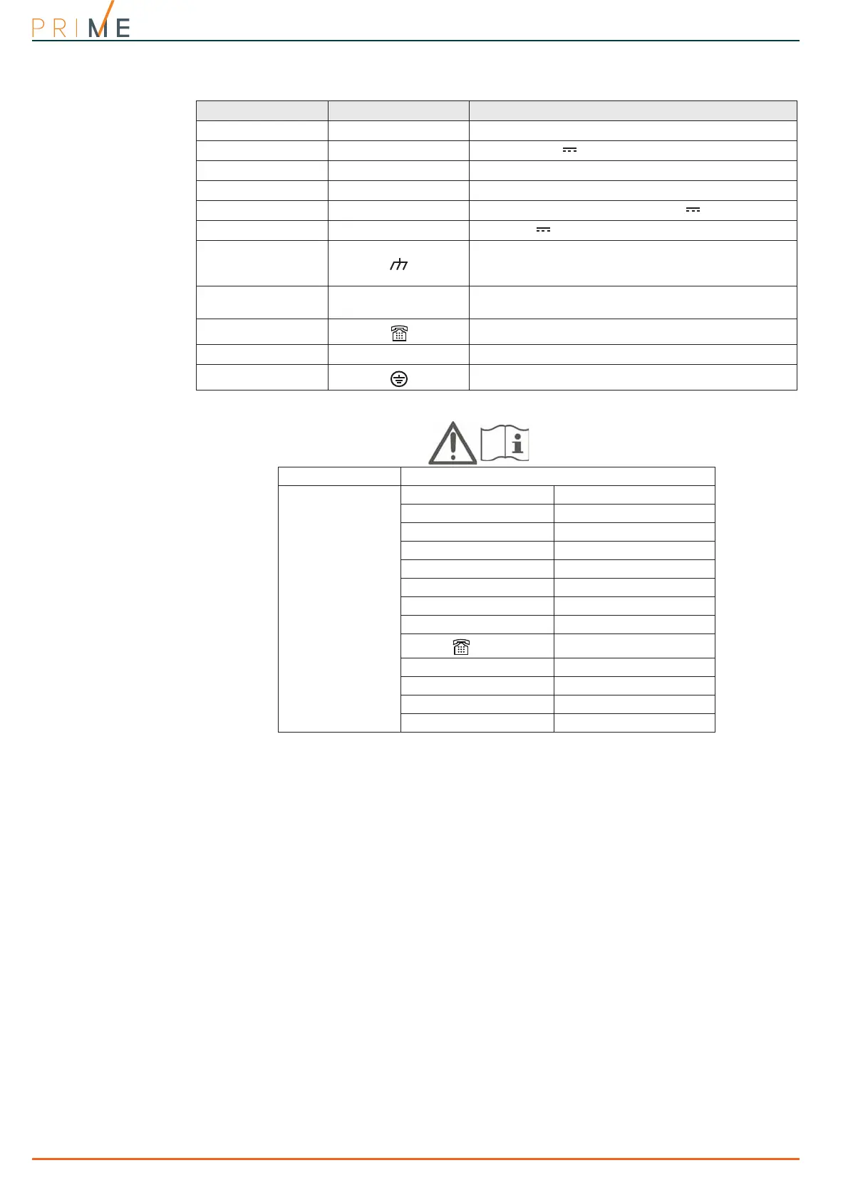
Table 2-7: Mother board - terminal board
n. icon/identifier function
1-2-3 NO NC COM
Voltage-free contacts of relay output
4+OC
13.8V
350mA ancillary power supply
5-6 OC1 OC2
Open-collector outputs
7-8-9-10 + D S -
I-BUS connection
11-23 AUX1 AUX2
13.8V output terminals
25 +12V
13.8V 350mA protected ancillary power supply
12-14-16-18-20-22-
24-26-28-30-32-34-
36
Power supply negative (earth or GND)
13-15-17-19-21-27-
29-31-33-35
T1-T2-T3-T4-T5-T6-
T7-T8-T9-T10
Control panel input/output terminals
37-38
Internal telephone-line connection
39-40 PSTN
Land-line connection (PSTN)
/
Earth connection
Table 2-8: EN IEC 62368-1
Insulation class I
Typ e of termi nals
AC input ES3, PS3
BAT-, BAT+ ES1, PS2
+ D S - ES1, PS2
AUXn, +12V ES1, PS2
NO, NC, COM ES1, PS2
Tn, OCn ES1, PS1
OUTn (Flex5/R, Flex2R/2T) ES3, PS3
Cn, NOn, NCn (AUXREL32) ES1, PS2
,
PSTN
ES2, PS1
RS232 ES1, PS1
Ethernet (PrimeLAN) ES1, PS1
USB ES1, PS1
ANT (Nexus, PrimeWiFi) ES1, PS1

 Loading...


