-28-
Introduction
Interface Name
Function Denition
AM600-CPU1608TP AM610-CPU1608TP
DB9 (CN1)/(female
socket)
Two RS485 ports
,
supporting the Modbus protocol.
DB9 (CN2)/(female
socket)
1. CANopen protocol
2. CANlink protocol
Probus-DP protocol
Network port (CN4) EtherCAT protocol None
Network port (CN3)
1. Modbus TCP
2. Standard Ethernet function
3. System program debugging
4. User program download and debugging (supporting only IPv4)
USB Program download and debugging
High-speed I/O
16-channel high-speed input
8-channel high-speed output
Input/output signal
indicator
16-channel input/8-channel output signal indicator
DIP switch RUN/STOP DIP switch
SD card interface Stores user programs and user data
MFK button MFK multi-function button
Indicator
RUN: running indicator
ERR: CPU running error indicator
SF: system error indicator
BF: bus error indicator
CANRUN: CANopen/CANlink running indicator None
CANERR: CANopen/CANlink error indicator None
LED Displays warning information and responses of the MFK button.
Local expansion bus
interface
A maximum of 16 I/O modules can be added. The number and conguration of the
modules vary depending on power consumption of the modules. The modules are not
hot-pluggable.
24 V power input terminal DC 24 V voltage input
,
used when the controller is powered by the AM600 power module.
Grounding switch
Switch of the connection between the internal digital ground and the housing ground.
By default
,
the switch is o. The switch is used only when the internal digital ground is
used as the reference plane. It is not recommended that you operate it to avoid aecting
system stability.
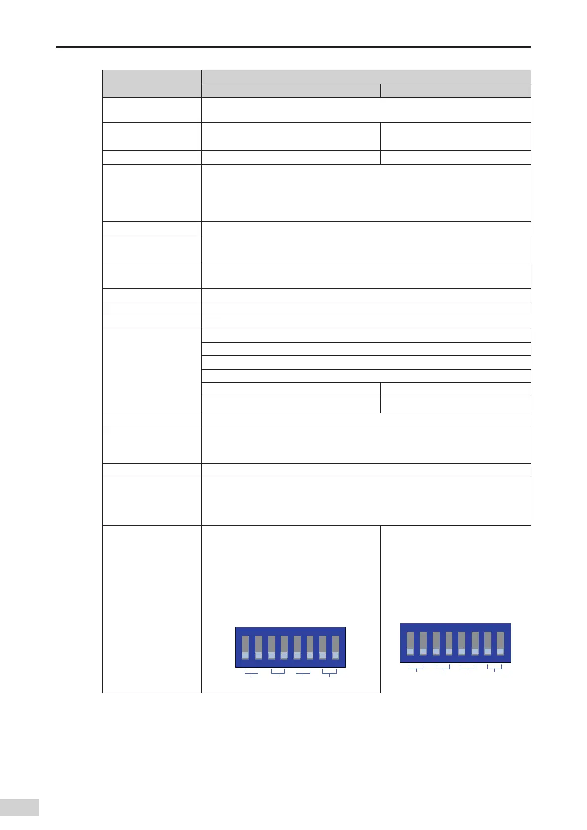
DIP switch of
communication
termination resistor
If a switch is set to ON
,
the termination resistor
is connected. By default
,
the switches are all
set to OFF. Switches 1 and 2 are for CAN-based
communication
,
switches 3 and 4 are for the
rst channel of RS485-based communication
,
switches 5 and 6 are for the second channel of
RS485-based communication
,
and switches 7
and 8 are reserved.
0/
$"/ 34 34 3FTFSWFE
If a switch is set to ON
,
the termination
resistor is connected. By default
,
the
switches are all set to OFF. Switches
3 and 4 are for COM1 communication
(RS485)
,
switches 5 and 6 are for COM0
communication (RS485)
,
and other
switches are reserved.
0/
3FTFSWFE 34 34 3FTFSWFE
 Loading...


