-83-
Introduction
4) Removal procedure: Unscrew the screws on the two sides of the DB9 connector
,
hold the plastic
part of the connector
,
and pull it out horizontally.
■
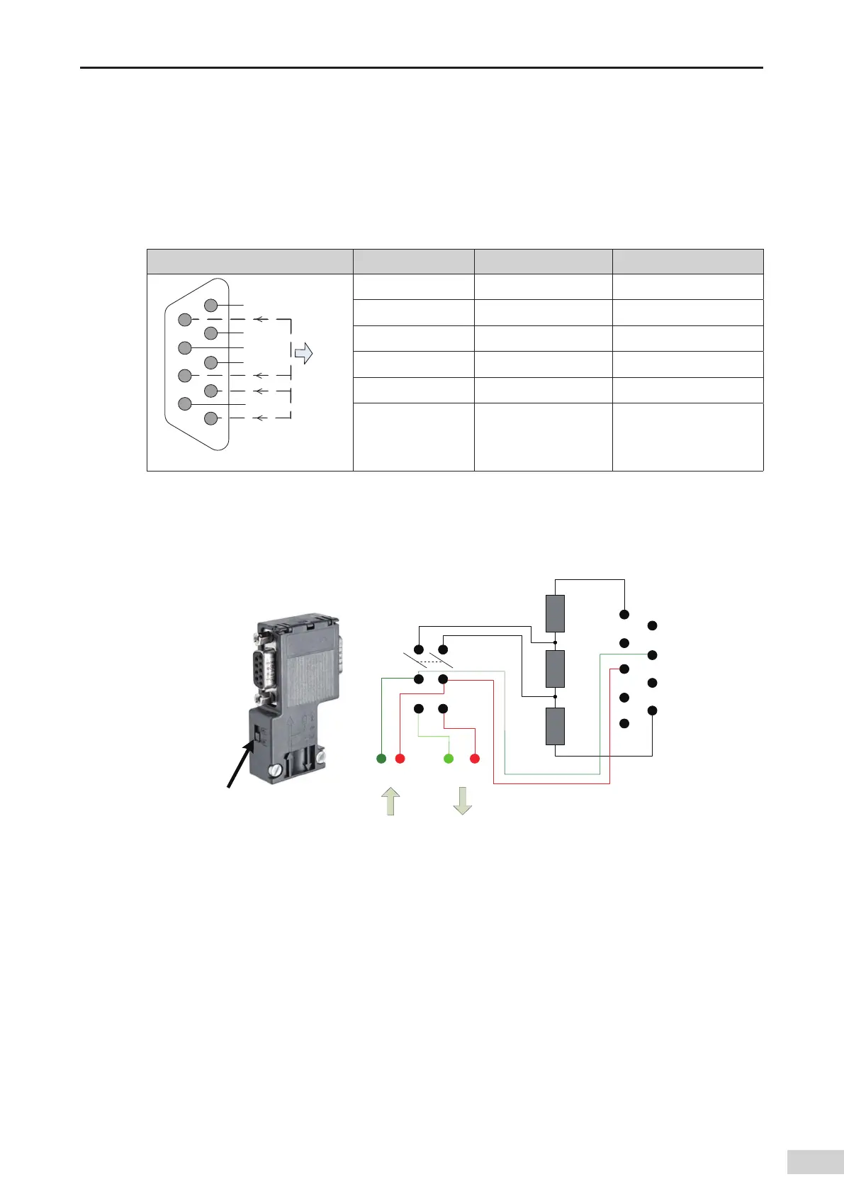
Standard Probus DB9 pin description
The Probus-DP module uses a standard DB9 socket to connect to the Probus master station. The pin
signals comply with the denition of the standard Siemens DB9 socket.
Control terminal function description:
Type Terminal Number Terminal Name Function
%BUBDBCMF#
354
(/%
7
6ODPOOFDUF
EJOUFSOBMMZ
%BUBDBCMF"
1
,
2
,
7
,
and 9 NC Not connected
3 Data cable B Data cable +
4 RTS Request to send
5 GND Isolated 5 V power ground
6 +5 V Isolated 5 V power
8 Data cable A Data cable -
■
Wiring
A DB9 connector (female socket) equipped with a termination resistor is used as the Probus-DP
communication connector. The connector is compatible with a universal Probus-DP interface. This
connector is designed and manufactured by Inovance
,
as shown in the following gure.
Bus
termination
resistor switch
Ē
Ē
Ē
(/%
%BUBDBCMF"
%BUBDBCMF#
7
3PDLFS
TXJUDI
0/
0''
" # " #
8JSJOHFOE
QJODPOOFDUPS
Figure 5-25 DB9 connector circuit
For Probus-DP
,
the theoretic transmission distance is 1000 m when the transmission rate is 9.6 Kbps.
The theoretic distance can be achieved only in standard Probus-DP test lab environment. If the
Probus-DP cable and Probus-DP connector are awless and the wiring is proper (separate from the
power cables)
,
the distance can reach 80% of the theoretic value. In reality
,
the distance is approximately
60% of the theoretic value. In addition
,
relay modules need to be added when the transmission
distance exceeds the threshold. Based on the preceding condition
,
in the AM600 project
,
the maximum
transmission distance of Probus-DP is set to 60% of the theoretic value. For details
,
see the following
table:
 Loading...


