- 116 -
voltage may cause over heat and even burning of the motor and stall over
current or current protection of the driver.
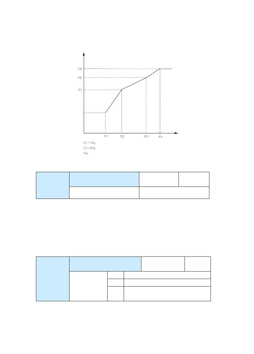
Fig.6-4 Schematic Diagram for V/F Curve Setup
Slip compensation
coefficient
Factory
default value
0.0%
F3-09
Setup range 0% ~ 200.0%
It is enabled only for V/F control. Setting this parameter can compensate the
slip in the V/F control mode due to load and reduce the change of rotation
speed of the motor following the load change. In general, 100% corresponds
to the rated slip of the motor with rated load. Slip coefficient adjustment can
refer to the following principles: When the load is rated load and the slip
compensation coefficient is set to 100%, the rotation speed of the motor in
the driver is close to the reference speed.
AVR(Automatic Voltage
Regulation)
Factory default
value
2
0 Inenabled
1 Enabled
F3-10
Setup range
2
Inenabled only at the time of
deceleration
In the V/F control mode, when it needs fast stop and there is no brake resistor,
selecting “Inenabled only at the time of deceleration” can greatly reduce the
Voltage %
Frequency Hz
Segments 1 to 3 Voltage Proportion of MS V/F
Segments 1 to 3 Frequency Point of MS V/F
Rated Motor Frequency F1=04
 Loading...

