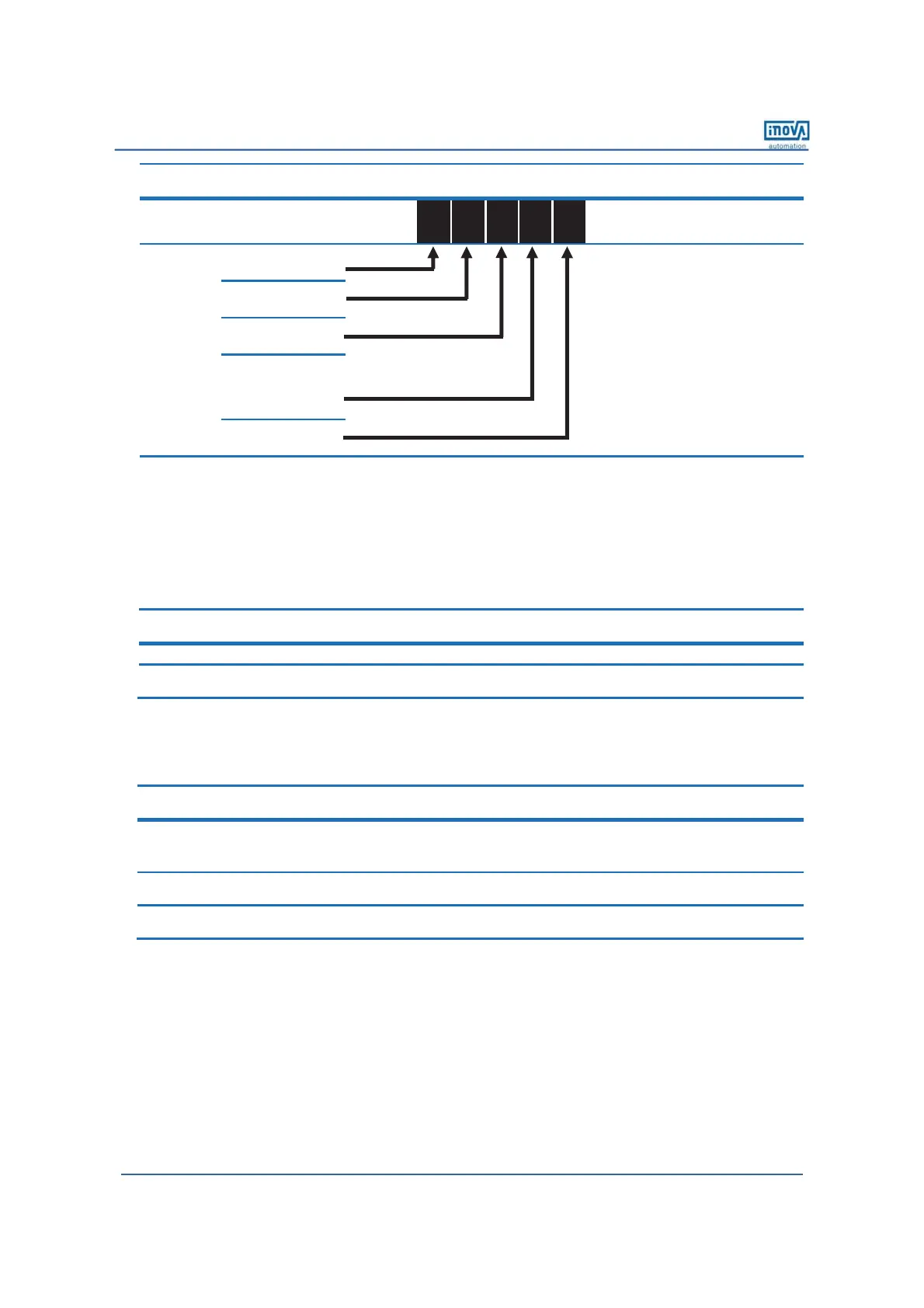
EasyManuals Logo

Inovance MD210 Series User Manual

Inovance MD210 Series
48 pages
To Next Page IconTo Next Page
To Previous Page IconTo Previous Page
Page #22 background imageLoading...
Page #22 background image
Page 20 of 43
Function
Code
Parameter Name
Setting Range
Unit
Default
Commission
F5-22
DO active mode
selection
7-segment
0
0
0
0
0
N.A.
00000
Reserved
Reserved
Reserved
Relay 1 active mode
0: Positive logic
ƿ
1: Negative logic
ƿ
Reserved
ƿ
: ‘Positive logic’ means that, when power on, the relay output terminal T/A-T/B is normally closed, and T/A-T/C is normally open.
‘Negative logic’ means the opposite situation.
However, no matter the logic is positive or negative, when power off, T/A-T/B is always normally closed, and T/A-T/C is always normally
open. F5-22 only changes the state of relay when power on.
Please pay particular attention to the switching of relay if F5-22=1.
9 Step 9: Set Startup Frequency If Needed
Function
Code
Parameter Name
Setting Range
Unit
Default
Commission
F6-03
Startup frequency
0.00 to 10.00
Hz
0.00
F6-04
Startup frequency
active time
0.0 to 100.0
s 0.0
9 Step 10: Set S-Curve If Needed
Function
Code
Parameter Name
Setting Range
Unit
Default
Commission
F6-07
Acceleration/
Deceleration mode
0: Linear mode
1: S-curve mode A
2: S-curve mode B
N.A. 0 1
F6-08
Time proportion of
S-curve start segment
0.0 to (100.0 minus F6-09)
% 30.0
F6-09
Time proportion of
S-curve end segment
0.0 to (100.0 minus F6-08)
% 30.0
efesotomasyon.com

Questions and Answers:

Question and Answer IconNeed help?

Do you have a question about the Inovance MD210 Series and is the answer not in the manual?

Inovance MD210 Series Specifications

General IconGeneral
BrandInovance
ModelMD210 Series
CategoryInverter
LanguageEnglish

Related product manuals