Do you have a question about the Inovance NICE1000 and is the answer not in the manual?
Safety precautions for installation, operation, and maintenance of the controller.
General precautions regarding motor insulation, thermal protection, heat, noise, and voltage.
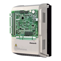
Details on product naming conventions and model identification for the NICE 1000.
Information on selecting and connecting Dynamic Brake Resistors for the NICE 1000 controller.
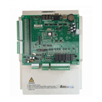
Covers power, DBR, main control board, and expansion board wiring instructions.
Guide to navigating and setting function codes using the keypad interface for parameter configuration.
Lists and describes various groups of function parameters available in the NICE 1000 system.
Instructions for safely powering down the control panel by switching off all breakers.
Procedure for setting the controller to inspection mode using a selector switch.
Steps for verifying control panel and field wiring integrity, including continuity and short circuit checks.
Steps to verify AC and DC voltage levels before powering up the controller.
Details the operational sequence of input/output signals on the main control board.
How to check the software version of the NICE 1000 controller.
Explains the input terminal functions and their status during initial lift startup.
Guide for adjusting motor and elevator running parameters using the LED keypad.
Procedures for tuning asynchronous and synchronous motors for optimal performance.
Steps and checks required for running the lift in inspection mode.
Procedure for the controller to learn the elevator shaft parameters for optimal operation.
Steps for commissioning the door operator system for auto and manual doors.
Verifying input signal status during normal lift operation.
How to adjust floor level settings for accurate car positioning.
Configuring car and landing call functions for different floor configurations.
Details on connecting and configuring digital load weigh systems.
Details on connecting and configuring analog load weigh systems.
Adjusting parameters to fine-tune starting jerk for improved ride comfort.
Fine-tuning speed loop gain parameters to reduce vibration during startup.
Adjusting current loop gain parameters to minimize vibration or jerk during operation.
Comprehensive table listing fault codes, probable causes, and remedies for system errors.
| Series | NICE1000 |
|---|---|
| Category | Controller |
| Enclosure Rating | IP20 |
| Output Voltage | 0 ~ Input Voltage |
| Control Method | V/F control, vector control |
| Overload Capacity | 150% for 60 seconds |
| Protection Features | Overcurrent, overvoltage, undervoltage, overload, short circuit |
| Humidity | 5% to 95% (non-condensing) |
| Altitude | Up to 1000m without derating |
| Cooling Method | Forced air cooling |
| Storage Temperature | -20°C to +65°C |