35
Power supply compatibility
Product Support: www.instron.com
You will need the following equipment (not supplied):
• Small flat-head screwdriver or probe
• Long-nose pliers
Electrical hazard - shut off the main power switch and disconnect the power to the frame
before changing the power setting. There are dangerous voltage levels inside the fuse
holder.
Hazard - Do not remove covers to any component of your system, unless it is
specified in a procedure.
There are dangerous voltages and rotating machinery inside the machine that may
cause bodily injury or damage to equipment.
1. Ensure that the power switch is in the Off (
0) position and disconnect the power cable
from the power source. Verify that no LEDs are illuminated on the frame control
panel.
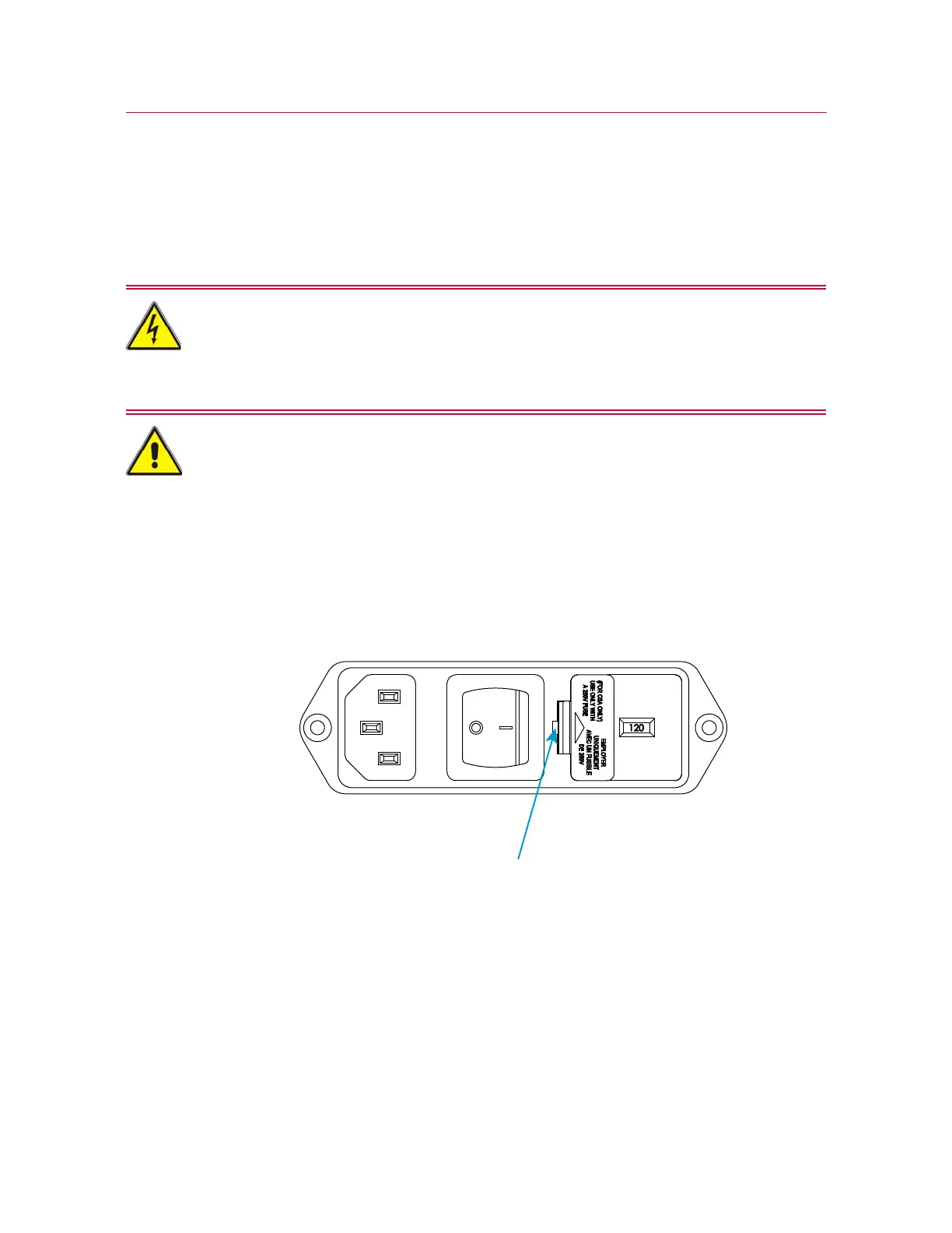
2. Insert a small flat-head screwdriver into the slot indicated in Figure 5 on page 35
and pry out the fuse holder.
Figure 5. Prying out the fuse holder
3. Remove the fuse holder (1) from the power input connector.
4. Using long-nose pliers, remove the voltage selector unit (see Figure 6 on page 36).