31
Product Support: www.instron.com
Chapter 3
Installation
• Level the load frame . . . . . . . . . . . . . . . . . . . . . . . . . . . . . . . . . . . . . . . . . . . . . . . . 31
• Power supply compatibility . . . . . . . . . . . . . . . . . . . . . . . . . . . . . . . . . . . . . . . . . . . 32
• System components . . . . . . . . . . . . . . . . . . . . . . . . . . . . . . . . . . . . . . . . . . . . . . . . 36
• First time startup . . . . . . . . . . . . . . . . . . . . . . . . . . . . . . . . . . . . . . . . . . . . . . . . . . . 47
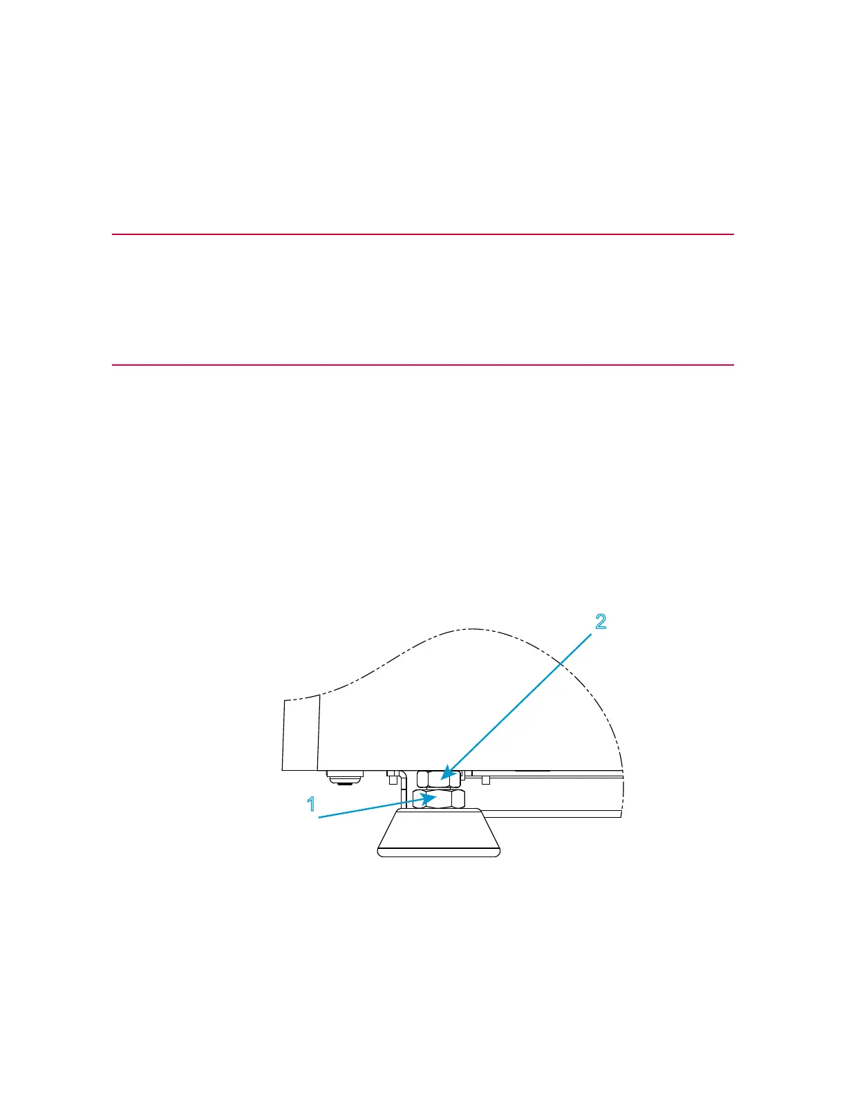
Level the load frame
Level the load frame immediately after you position it for installation. This prevents the
base from rocking and provides a level test surface for more accurate results.
Refer to Figure 3 on page 31 and follow the procedure.
Figure 3. Adjust the leveling feet
You need the following equipment (supplied in the ancillary parts kit unless specified
otherwise):