Chapter: Installation
38 M10-17318-EN
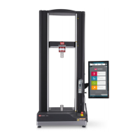
2 Ground connection (when required) “Ground connection detail”
on page 41
3To Bluehill
®
Operator Dashboard or
separate computer (not shown in
Figure 7)
4 System ID label
5 and 6 Exhaust vents Leave at least 152 mm (6 in)
of space behind the frame to
allow for ventilation and
periodic access.
7 Cable clip Use T-nut, cable clips, cable
tie hooks and loops to secure
load cell cables and
pneumatic grip connections
8Rear panel “Rear panel connections
detail” on page 39
9 Controller panel “Controller connections
detail” on page 40
10 Adjustable feet “Level the load frame” on
page 31
11 Power inlet connection, power switch,
fuses and voltage selector
“Power supply
compatibility” on page 32
Label Component More detail