Technical Reference
49
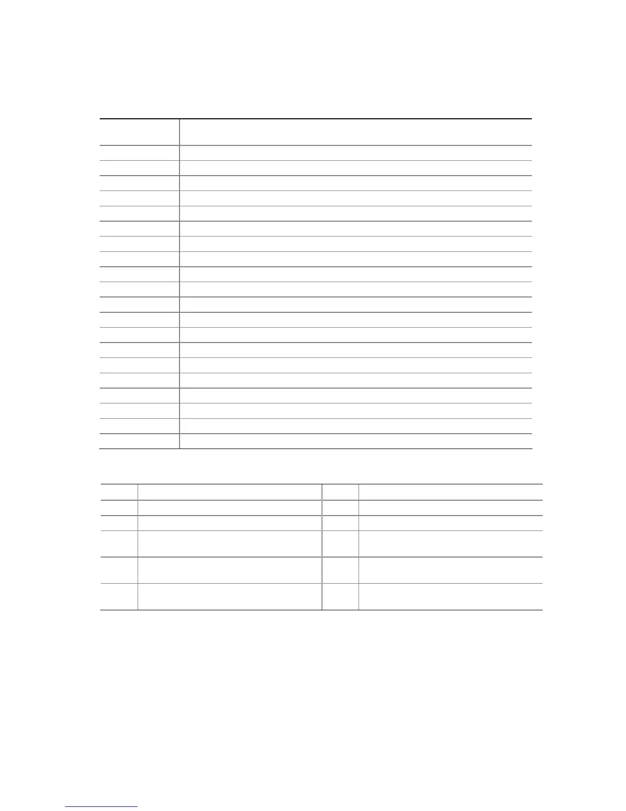
Table 16 lists the component-side connectors identified in Figure 16.
Table 16. Component-side Connectors Shown in Figure 16
Item/callout
from Figure 16
Description
A
Front panel audio connector
B
PCI Conventional bus add-in card connector 2
C
PCI Conventional bus add-in card connector 1
D
Rear chassis fan connector
E
+12V power connector (ATX12V)
F
Processor fan connector
G
Power connector
H
Diskette drive connector
I
Parallel ATA IDE connector
J
Chassis intrusion connector
K
Front chassis fan connector
L
Serial ATA connector 1
M
Serial ATA connector 3
N
Serial ATA connector 2
O
Serial ATA connector 0
P
Auxiliary front panel power LED connector
Q
Front panel connector
R
Front panel USB connector
S
Front panel USB connector
T
PCI Express x1 bus add-in card connector
Table 17. Front Panel Audio Connector
Pin Signal Name Pin Signal Name
1 Port E [Port 1] Left Channel 2 Ground
3 Port E [Port 1] Right Channel 4 Presence# (dongle present)
5 Port F [Port 2] Right Channel 6 Port E [Port 1] Sense return
(jack detection)
7 Port E [Port 1] and Port F [Port 2]
Sense send (jack detection)
8 Key
9 Port F [Port 2] Left Channel 10 Port F [Port 2] Sense return
(jack detection)
#
INTEGRATOR’S NOTE
The front panel audio connector is colored yellow.