Intel Desktop Board D915GLVG Technical Product Specification
52
2.8.2.2 Add-in Card Connectors
The board has the following add-in card connectors:
• One PCI Express x1 bus add-in card connector. The x1 interface supports simultaneous
transfer speeds up to 500 MBytes/sec.
• Two PCI Conventional (rev 2.2 compliant) bus add-in card connectors. The SMBus is routed
to PCI Conventional bus connector 2 only (ATX expansion slot 6). PCI Conventional bus
add-in cards with SMBus support can access sensor data and other information residing on the
board.
Note the following considerations for the PCI Conventional bus connectors:
• All of the PCI Conventional bus connectors are bus master capable.
• SMBus signals are routed to PCI Conventional bus connector 2. This enables PCI
Conventional bus add-in boards with SMBus support to access sensor data on the boards. The
specific SMBus signals are as follows:
⎯ The SMBus clock line is connected to pin A40.
⎯ The SMBus data line is connected to pin A41.
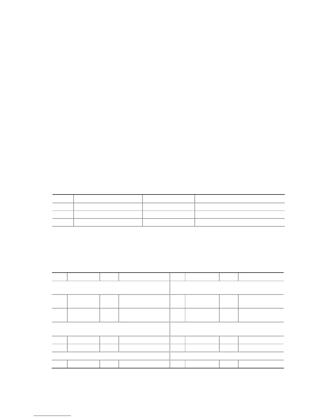
2.8.2.3 Auxiliary Front Panel Power/Sleep LED Connector
Pins 1 and 3 of this connector duplicate the signals on pins 2 and 4 of the front panel connector.
Table 24. Auxiliary Front Panel Power/Sleep LED Connector
Pin Signal Name In/Out Description
1 HDR_BLNK_GRN Out Front panel green LED
2 Not connected
3 HDR_BLNK_YEL Out Front panel yellow LED
2.8.2.4 Front Panel Connector
This section describes the functions of the front panel connector. Table 25 lists the signal names of
the front panel connector. Figure 17 is a connection diagram for the front panel connector.
Table 25. Front Panel Connector
Pin Signal In/Out Description Pin Signal In/Out Description
Hard Drive Activity LED
[Yellow]
Power LED
[Green]
1 HD_PWR Out Hard disk LED pull-up
(750
Ω) to +5 V
2 HDR_BLNK_
GRN
Out Front panel green
LED
3 HAD# Out Hard disk active LED 4 HDR_BLNK_
YEL
Out Front panel yellow
LED
Reset Switch
[Purple]
On/Off Switch
[Red]
5 Ground Ground 6 FPBUT_IN In Power switch
7 FP_RESET# In Reset switch 8 Ground Ground
Power Not Connected
9 +5 V Power 10 N/C Not connected