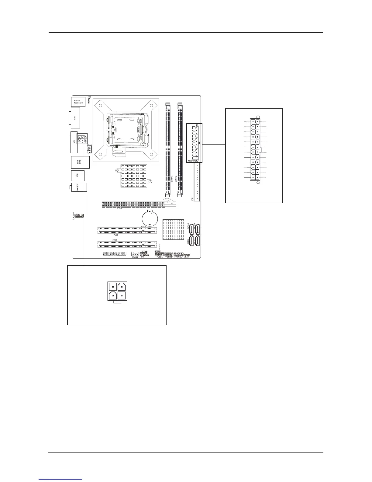
3.11 Power Connectors
ATXPWR (ATX Power) connector
We recommend to use our motherboard with a power supply that complies with the ATX12V
Power Supply Design Guide Version 1.1. Every ATX12V power supply unit has a standard
24-pin ATX main power connector that must be plugged into this connector. If you would like
to use an old power supply with only a 20-pin ATX main power connector, then please plug
the 20-pin ATX main power connector along with pin 1 and pin 13.
Figure 1: Reference for 4 pin PWR12V.
PWR12V (+12V Power) connector
Your power supply unit may come with a 4-pin +12V power connector. The +12V
power enables the delivery of more +12VDC current to the CPU's Voltage Regulator Module
(VRM). If available, please use the 8-pin power; otherwise please connect the 4-pin power to
this connector.