Datasheet 17
Electrical Specifications
V
CTERM
System bus termination voltage.
GND System ground.
N/C No connection can be made to these pins.
TERMA, TERMB The Itanium 2 processor uses two pins to control the on-die termination
function, TERMA and TERMB. Both of these termination pins must be
pulled to VCTERM in order to terminate the system bus using the on-die
termination resistors. Both of these termination pins must be pulled to
GND in order to use off-die termination.
TUNER1, TUNER2 TUNER1 is used to control the slew rate of the system bus I/O buffers.
The nominal value for the TUNER1 resistor is 150 ohms. A lower
resistance will cause a faster slew rate. TUNER2 is used to control the
termination resistance for the system bus I/O buffers. The nominal value
for the TUNER2 resistor is 150 ohms. A lower resistance will cause a
lower on-die termination resistance. On-die termination mode will only
be selected if the TERMA and TERMB pins are terminated as indicated
above.
VCCMON, VSSMON These pins provide a remote sense connection from the processor to the
power pod. No connections that constitute a current load can be made to
these pins.
2.3 Package Specifications
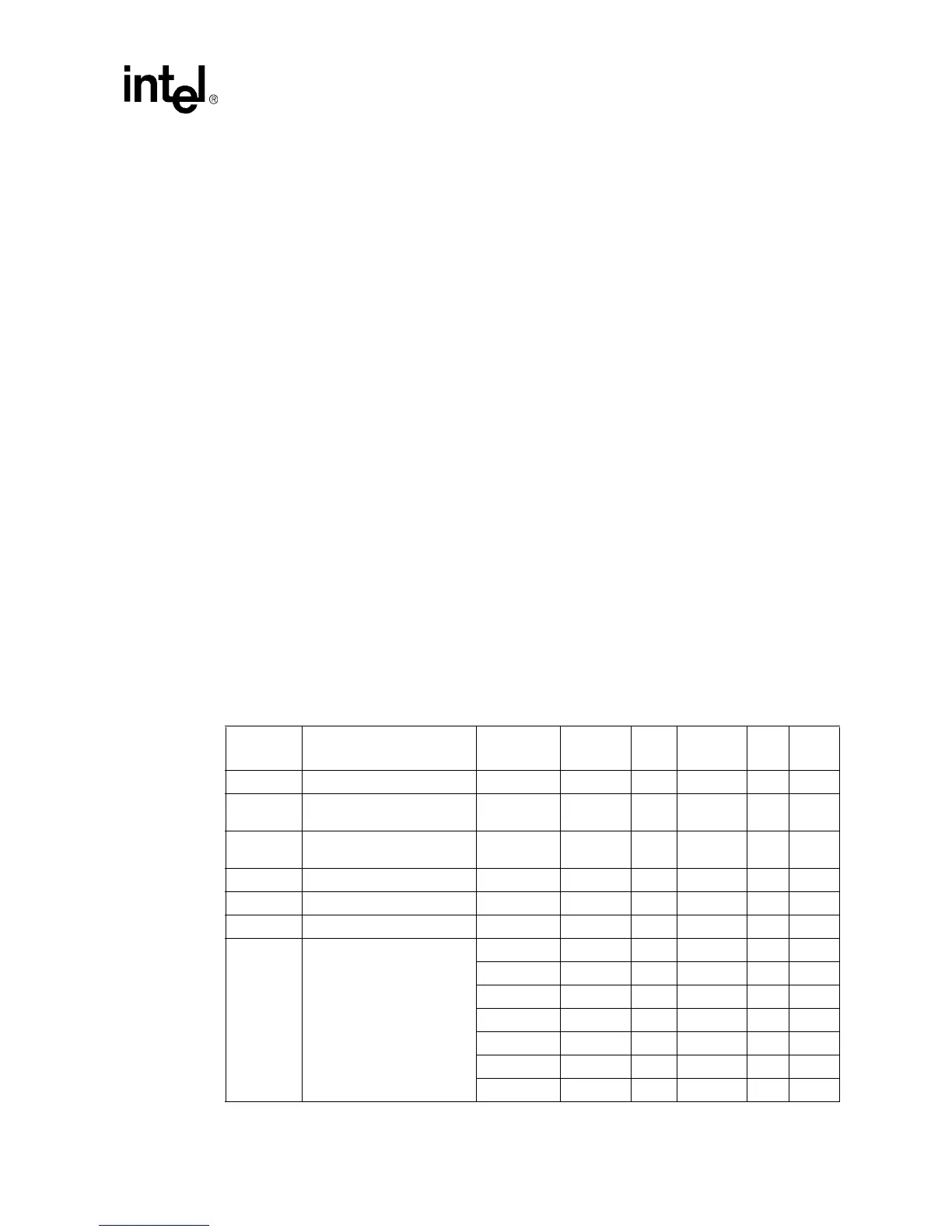
Table 2-2 through Table 2-9 list the DC voltage, current and power specifications for the Itanium 2
processor. The voltage and current specifications are defined at the Itanium 2 processor pins.
Operational specifications listed in Table 2-2 through Table 2-9 are only valid while meeting
specifications for case temperature, clock frequency, and input voltages.
Table 2-2. Itanium
®
2 Processor Package Specifications
Symbol Parameter
Core
Frequency
Minimum Typ Maximum Unit Notes
V
CTERM
Termination Voltage All 1.2 –1.5% 1.2 1.2 +1.5% V
1
R
TERM
Recommended Termination
Resistance
All 45 W
2
V
TAP
Test Access Port Voltage
(VCC
TAP
)
All 1.2 –1.5% 1.2 1.5 V
I
CTERM
Termination Voltage Current All 7.2 A
3
PWR
MAX
Maximum Processor Power All 130 W
4
PWR
TDE
Thermal Design Envelope All 130 W
5
PWR
TDP
Thermal Design Power 900 MHz 90 W
6
1.0 GHz 100 W
6
1.3 GHz 97 W
6
1.4 GHz 91 W
6
1.5 GHz 107 W
6
1.6 GHz 122 W
6
1.66 GHz 122 W
6