34 Datasheet
Electrical Specifications
Warm Reset Sequence:
• PWRGOOD remains high throughout the entire sequence as power is already available and
stable to the processor.
• The bus ratio configuration pins (A[21:17]#) must be asserted the entire time RESET# is
asserted.
• The duration from the assertion of RESET# to the deassertion of RESET# must be 1
millisecond minimum.
• After RESET# is deasserted, the configuration pins must remain valid for two BCLKs
(minimum) to three BCLKs (maximum).
• BCLK is shown as a time reference to the BCLK period. It is not a requirement that this is
BCLKn or BCLKp signal.
• Configuration signals other than A[21:17]# must be asserted four BCLKs prior to the
deasserted edge of RESET# and must remain valid for two BCLKs (minimum) to three
BCLKs (maximum) after the deasserted edge of RESET#.
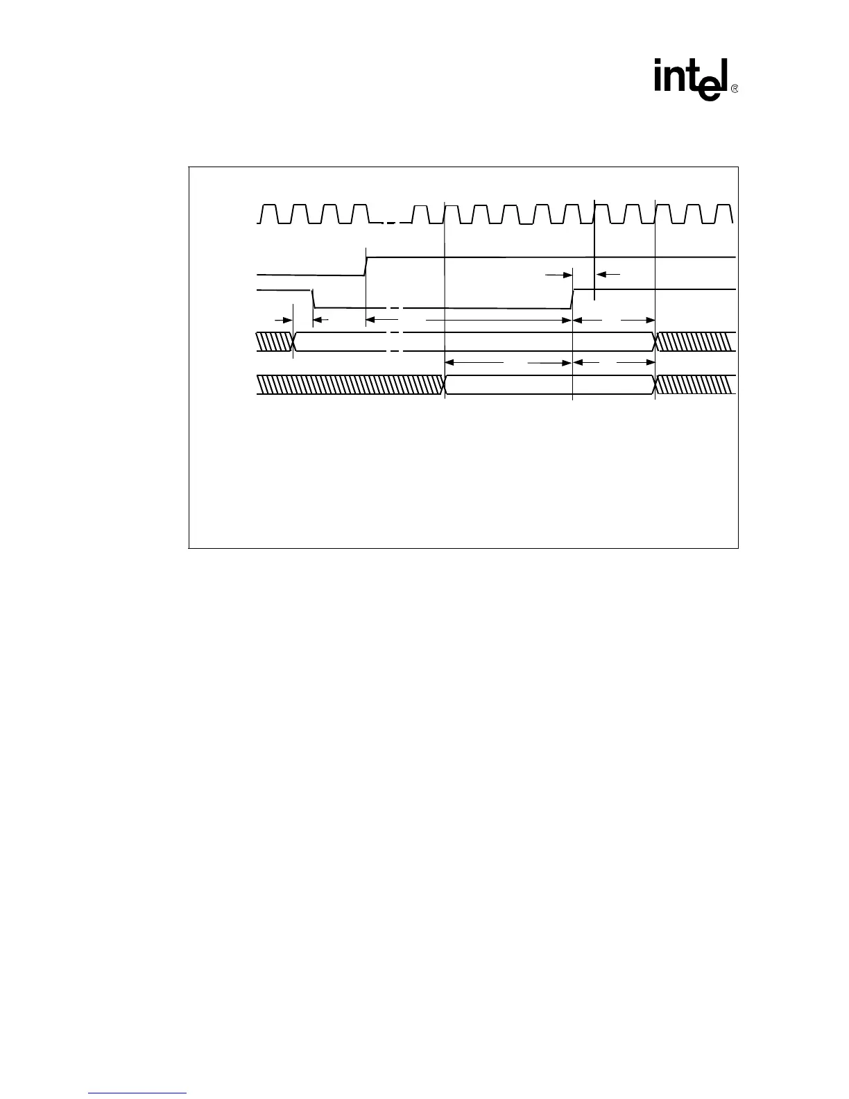
Figure 2-7 outlines the timing relationship between the bus ratio configuration pins, RESET# and
PWRGOOD for warm reset.
Figure 2-6. System Bus Reset and Configuration Timings for Cold Reset
000859b
BCLK
PWRGOOD
RESET#
Bus Ratio
(A[21:17]#)
T
A
= 1.15 ns minimum; (set up time to BCLK for deassertion edge of RESET#)
T
B
= 1 ms minimum for cold reset
T
D
= 2 BCLKs minimum, 3 BCLKs maximum
T
E
= 4 BCLKs minimum
T
F
= 2 BCLKs minimum, 3 BCLKs maximum
Additional
Configuration
Signals
T
B
T
D
T
E
T
F
T
A
t
1
t
2
t
3
T
C
T
C
= Bus ratio signals must be asserted no later than RESET#
t
-2
t
-1
t
0
t
-4
t
-3