36 Datasheet
Electrical Specifications
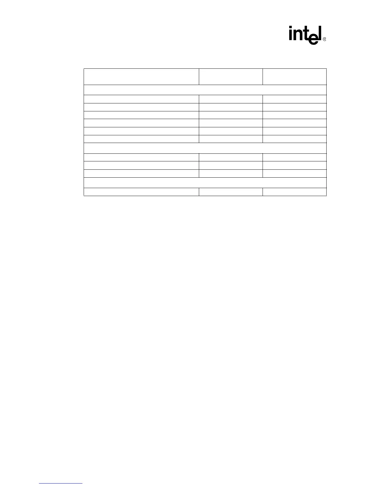
System Management Signals
3.3V GND
SMA[2:0] N/C
SMSC N/C
SMSD N/C
SMWP N/C
THRMALERT# H
1,
4
LVTTL Power Pod Signals
OUTEN Must be used
PPODGD# Must be used
CPUPRES# Must be used
Reserved Pins
N/C N/C
NOTES:
1. L = GND, H = V
CTERM
.
2. AGTL+ output signals SBSY[0:1]#, DBSY[0:1]#, and DRDY[0,1]# may be left as N/C if not used on platform.
3. Should be properly terminated through a resistor.
4. THRMALERT# should be pulled up to 3.3V through a resistor.
Table 2-26. Connection for Unused Pins (Sheet 2 of 2)
Pins/Pin Groups
Recommended
Connections
Notes