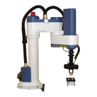
3. Refer to Figure 4-8.
•
Connect the two
transparent 1/4" O.D.
hoses from the robot to
the CYL ports on the
pneumatic valve.
•
Connect a 5 bar/90 PSI
air supply to the IN port
on the valve.
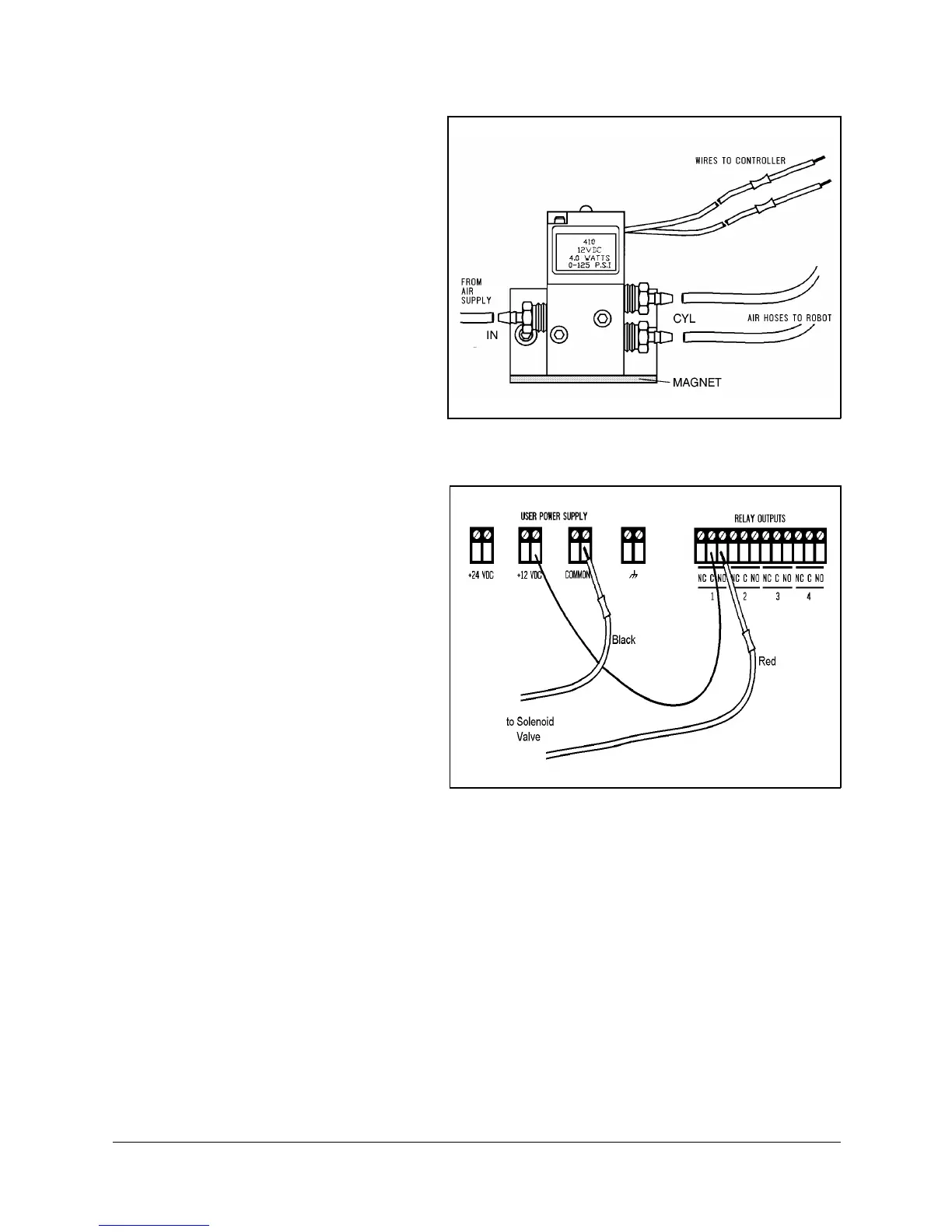
4. Refer to Figure 4-9.
Connect the valve to the
controller’s User Power
Supply as follows:
•
Connect the black wire
to a common terminal.
•
Connect the red wire to
the normally open (NO)
terminal of any unused
relay output.
5. Connect 12VDC or 24VDC
(in accordance with your
valve’s specification) to the
common (C) terminal of the
same relay output, as
shown in Figure 4-9.
6. Attach the valve to the
controller or any other
metalic surface by means of
the valve’s magnetic base.
Figure 4-9: Valve—Controller Connections
Figure 4-8: Pneumatic Solenoid Valve
SCORA-ER 14 4-6 User’s Manual
9603
 Loading...