SAVE THESE INSTRUCTIONS
Page 6
(257IO) MODEL FP602 FILTER PUMP ENGLISH SIZE: 4.875” X 7.25” PANTONE 295U 05/20/2024
257
A
English
WARNING
Position this product away from the pool, so as to prevent
children from climbing on it and accessing the pool.
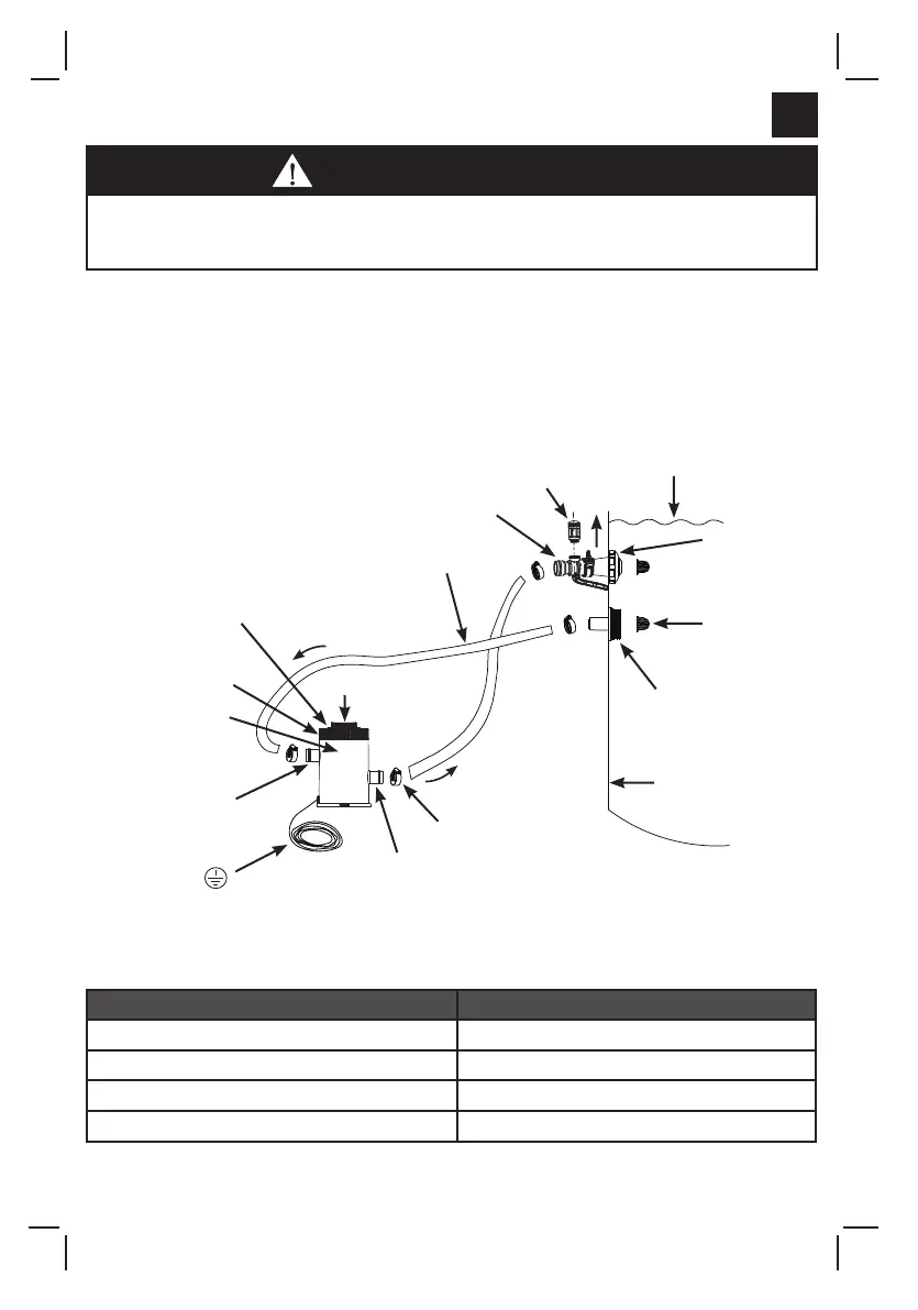
SETUP INSTRUCTIONS (continued)
(ILLUSTRATION NOT TO SCALE)
W
AT
E
R
D
I
R
E
C
TIO
N
HOSE CLAMP
UPPER PUMP
CONNECTION
FILTER CARTRIDGE
INSIDE
W
A
T
E
R
D
I
R
E
C
T
I
O
N
WATER LEVEL
AIR JET
VALVE
POOL INLET
AIR ADAPTOR
POOL INLET
JET NOZZLE
(REMOVE)
PLUG
STRAINER GRID
(REMOVE)
INSIDE OF POOL
HOSE
AIR RELEASE VALVE
THREADED FILTER
HOUSING COLLAR
FILTER HOUSING
COVER
LOWER PUMP
CONNECTION
It is essential to change any damaged element or set of elements as soon as possible.
Use only parts approved by the manufacturer.
To inspect and change the filter cartridge, disconnect line cord, unscrew the pool inlet
nozzle
(10)
and strainer grid
(11)
from the strainer connectors and insert the hat-like plugs
into the strainer connectors before servicing the filter. After service, open the air release
valve, remove the plugs, allow any air to escape through the valve before tightening the
valve again and replace the pool inlet nozzle
(10)
and strain grid
(11)
. The pump is now
primed with water again and may be turned on.
The power cord plug to the 220-240 volt electrical power source of the filter pump must be
positioned more than 3.5 m away from the pool walls. Check your local authorities to
determine the appropriate standard and requirements for “electrical installation of swimming
pools and basins equipment”. The following table is for reference only:
International
France
Germany
TheNetherlands
Country/Region
Standard Number
IEC 60364-7-702
NFC15-100-7-702
DINVDE0100-702
NEN1010-702