Version 1.00 | Optidrive ODE-3 User Guide | 15www.invertekdrives.com
Power & Control Wiring
4
4.9. EMC Compliant Installation
Category Supply Cable Type Motor Cable Type Control Cables
Maximum Permissible
Motor Cable Length
C1
6
Shielded
1
Shielded
1,5
Shielded
4
1M / 5M
7
C2 Shielded
2
Shielded
1, 5
5M / 25M
7
C3 Unshielded
3
Shielded
2
25M / 100M
7
1
A screened (shielded) cable suitable for fixed installation with the relevant mains voltage in use. Braided or twisted type screened
cable where the screen covers at least 85% of the cable surface area, designed with low impedance to HF signals. Installation of
a standard cable within a suitable steel or copper tube is also acceptable.
2
A cable suitable for fixed installation with relevant mains voltage with a concentric protection wire. Installation of a standard cable
within a suitable steel or copper tube is also acceptable.
3
A cable suitable for fixed installation with relevant mains voltage. A shielded type cable is not necessary.
4
A shielded cable with low impedance shield. Twisted pair cable is recommended for analog signals.
5
The cable screen should be terminated at the motor end using an EMC type gland allowing connection to the motor body
through the largest possible surface area. Where drives are mounted in a steel control panel enclosure, the cable screen may be
terminated directly to the control panel using a suitable EMC clamp or gland, as close to the drive as possible.
6
Compliance with category C1 conducted emissions only is achieved. For compliance with category C1 radiated emissions,
additional measures may be required, contact your Sales Partner for further assistance.
7
Permissible cable length with additional external EMC filter.
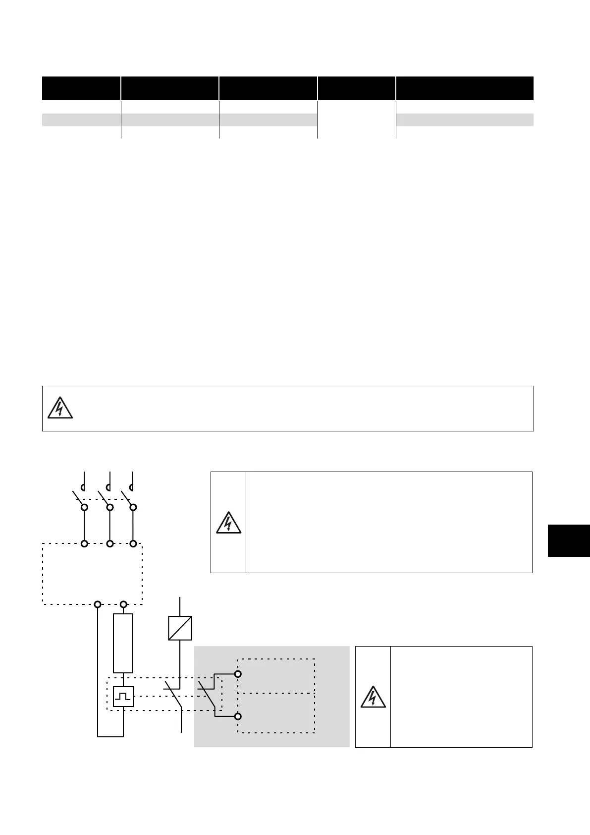
4.10. Optional Brake Resistor
Optidrive E3 Frame Size 2 and above units have a built in Brake Transistor. This allows an external resistor to be connected to the
drive to provide improved braking torque in applications that require this.
The brake resistor should be connected to the “+” and “BR” terminals as shown.
The voltage level at these terminals may exceed 800VDC.
Stored charge may be present after disconnecting the mains power.
Allow a minimum of 10 minutes discharge after power off before attempting any connection to these terminals.
Suitable resistors and guidance on selection can be obtained from your Invertek Sales Partner.
Dynamic Brake Transistor with Thermal Overload Protection
L1/L
K1
ODE-3
DC+
K1 - Main Contractor
Thermal Overload / Brake Resistor with internal Over Temperature switch
BR
L2/N L3
Dlx
+ 24 VDC
ODE-3
Optional wiring
It is highly recommended to equip the drive with a main contractor and
provide and use an additional thermal overload protection for braking
resistor.
The contractor should be wired so that it opens in case the resistor overheats,
otherwise the drive will not be able to interrupt the main supply if the brake
chopper remains closed (short-circuited) in a faulty situation.
It is also recommended to wire the thermal overload protection to a digital
input of the drive as an External Trip.
The voltage level at these terminals
may exceed 800VDC.
Stored charge may be present after
disconnecting the mains power.
Allow a minimum of 5 minutes
discharge after power off before
attempting any connection to these
terminals.
 Loading...

