Version 1.00 | Optidrive ODE-3 User Guide | 9www.invertekdrives.com
Mechanical Installation
3
3. Mechanical Installation
3.1. General
The Optidrive should be mounted in a vertical position only, on a flat, flame resistant, vibration free mounting using the integral
mounting holes or DIN Rail clip (Frame Sizes 1 and 2 only).
IP20 Optidrives must be installed in a pollution degree 1 or 2 environment only.
Do not mount flammable material close to the Optidrive.
Ensure that the ambient temperature range does not exceed the permissible limits for the Optidrive given in section 9.1.
Environmental.
Provide suitable clean, moisture and contaminant free cooling air sufficient to fulfil the cooling requirements of the Optidrive.
3.2. UL Compliant Installation
Refer to section 9.4. Additional Information for UL Compliance on page 35 for Additional Information for UL Compliance.
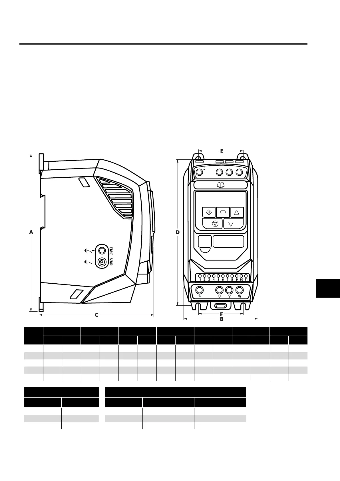
3.3. Mechanical Dimensions and Mounting – IP20 Open Units
L1/ L
L3
L2/N
Drive
Size
A B C D E F Weight
mm in mm in mm in mm in mm in mm in Kg Ib
1 173 6.81 83 3.27 123 4.84 162 6.38 50 1.97 50 1.97 1.0 2.2
2 221 8.70 110 4.33 15 0 5.91 209 8.23 63 2.48 63 2.48 1.7 3.8
3 2 61 10.28 131 5.16 175 6.89 247 9.72 80 3.15 80 3 .15 3.2 7.1
4 420 16.54 171 6.73 212 8.35 400 15 . 75 125 4.92 125 4.92 9.1 20.1
5 486 19 .13 222 8 . 74 226 8.89 463 18.22 175 6.88 175 6.88 18 .1 39.9
Mounting Bolts Tightening Torques
Frame Size Frame Size Control Terminals Power Terminals
1 - 3 4 x M5 (#8) 1 - 3 0.5 Nm (4.5 lb-in) 1 Nm (9 lb-in)
4 4 x M8 4 0.5 Nm (4.5 lb-in) 2 Nm (18 lb-in)
5 4 x M8 5 0.5 Nm (4.5 lb-in) 4 Nm (35.5 lb-in)
 Loading...

