Version 1.00 | Optidrive ODE-3 User Guide | 25www.invertekdrives.com
6.3. Advanced Parameters
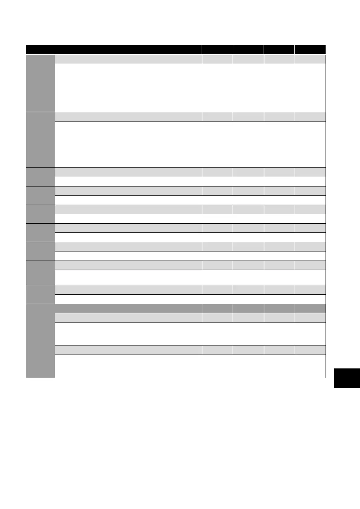
Par. Description Minimum
Maximum
Default Units
P-51 Motor Control Mode 0 5 0 -
0: Vector speed control mode
1: V/f mode
2: PM motor vector speed control
3: BLDC motor vector speed control
4: Synchronous Reluctance motor vector speed control
5: LSPM motor vector speed control
P-52 Motor Parameter Autotune 0 1 0 -
0: Disabled
1: Enabled. When enabled, the drive immediately measures required data from the motor for optimal operation. Ensure all motor
related parameters are correctly set first before enabling this parameter.
This parameter can be used to optimise the performance when P-51 = 0.
Autotune is not required if P-51 = 1.
For settings 2 – 5 of P-51, autotune MUST be carried out AFTER all other required motor settings are entered.
P-53 Vector Mode Gain 0.0 200.0 50.0 %
Single Parameter for Vector speed loop tuning. Affects P & I terms simultaneously. Not active when P-51 = 1.
P-54 Maximum Current Limit 0.0 175.0 150.0 %
Defines the max current limit in vector control modes
P- Motor Stator Resistance 0.00 655.35 -
Motor stator resistance in Ohms. Determined by Autotune, adjustment is not normally required.
P-56 Motor Stator d-axis Inductance (Lsd) 0.00 655.35 - mH
Determined by Autotune, adjustment is not normally required.
P-57 Motor Stator q-axis Inductance (Lsq) 0.00 655.35 - mH
Determined by Autotune, adjustment is not normally required.
P-58 DC Injection Speed 0.0 P-01 0.0 Hz / RPM
Sets the speed at which DC injection current is applied during braking to Stop, allowing DC to be injected before the drive reaches
zero speed if desired.
P-59 DC Injection Current 0.0 100.0 20.0 %
Sets the level of DC injection braking current applied according to the conditions set in P-32 and P-58.
P-60 Motor Overload Management - - - -
Index 1: Thermal Overload Retention 0 1 1 1
0: Disabled
1: Enabled. When enabled, the drive calculated motor overload protection information is retained after the mains power is
removed from the drive.
Index 2: Thermal Overload Limit Reaction 0 1 1 1
0: It.trp. When the overload accumulator reaches the limit, the drive will trip on It.trp to prevent damage to the motor.
1: Current Limit Reduction. When the overload accumulator reaches 90% of, the output current limit is internally reduced to
1
00% of P-08 in order to avoid an It.trp. The current limit will return to the setting in P-54 when the overload accumulator reaches 10%.
Parameters
6
 Loading...

