Version 1.00 | Optidrive ODE-3 User Guide | 31www.invertekdrives.com
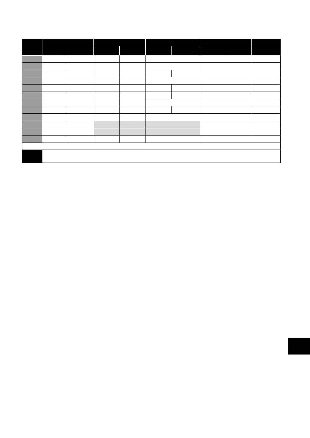
7.7. Macro Functions - User PI Control Mode (P-12 = 5 or 6)
P-15
DI1 DI2 DI3 / AI2 DI4 / AI1 Diagram
0 1 0 1 0 1 0 1
0 STOP ENABLE PI REF P-20 REF AI2 AI1 4
1 STOP ENABLE PI REF AI1 REF AI2 (PI FB) AI1 4
3, 7 STOP ENABLE PI REF P-20 E-TRIP OK AI1 (PI FB) 3
4 (NO) START (NC) STOP AI2 (PI FB) AI1 12
5 (NO) START (NC) STOP PI REF P-20 REF AI1 (PI FB) 5
6 (NO) START (NC) STOP E-TRIP OK AI1 (PI FB)
8 STOP RUN
FWD REV
AI2 (PI FB) AI1 4
14 STOP RUN - - E-TRIP OK AI1 (PI FB) 16
15 STOP RUN P-23 REF PI REF Fire Mode AI1 (PI FB) 1
16 STOP RUN P-23 REF P-21 REF Fire Mode AI1 (PI FB) 1
17 STOP RUN P-21 REF P-23 REF Fire Mode AI1 (PI FB) 1
18 STOP RUN AI1 REF PI REF Fire Mode AI1 (PI FB) 1
2, 9, 10, 11, 12, 13 = Behavior as per setting 0
NOTE
P1 Setpoint source is selected by P-44 (default is fixed value in P-45, AI 1 may also be selected).
P1 Feedback source is selected by P-46 (default is AI 2, other options may be selected).
7.8. Fire Mode
The Fire Mode function is designed to ensure continuous operation of the drive in emergency conditions until the drive is no longer
capable of sustaining operation. The Fire Mode input may be a normally open (Close to Activate Fire Mode) or Normally Closed
(Open to Activate Fire Mode) according to the setting of P-30 Index 2. In addition, the input may be momentary or maintained type,
selected by P-30 Index 3.
This input may be linked to a fire control system to allow maintained operation in emergency conditions, e.g. to clear smoke or
maintain air quality within that building.
The fire mode function is enabled when P-15 = 15, 16 or 17, with Digital Input 3 assigned to activate fire mode.
Fire Mode disables the following protection features in the drive:
(Heat-sink Over-Temperature), (Drive Under Temperature), L (Faulty Thermistor on Heat-sink), (External Trip),
(4-20mA fault), (Phase Imbalance), L (Input Phase Loss Trip), C (Communications Loss Trip), .
(Accumulated overload Trip).
The following faults will result in a drive trip, auto reset and restart:
Vl (Over Voltage on DC Bus), Vl (Under Voltage on DC Bus), (Fast Over-current Trip), (Instantaneous over
current on drive output), (Drive output fault, Output stage trip).
Analog and Digital Input Macro Configurations
7
 Loading...

