Version 1.00 | Optidrive ODE-3 User Guide | 13www.invertekdrives.com
4.5. Motor Terminal Box Connections
Most general purpose motors are wound for operation on dual voltage supplies. This is indicated on the nameplate of the motor. This
operational voltage is normally selected when installing the motor by selecting either STAR or DELTA connection. STAR always gives
the higher of the two voltage ratings.
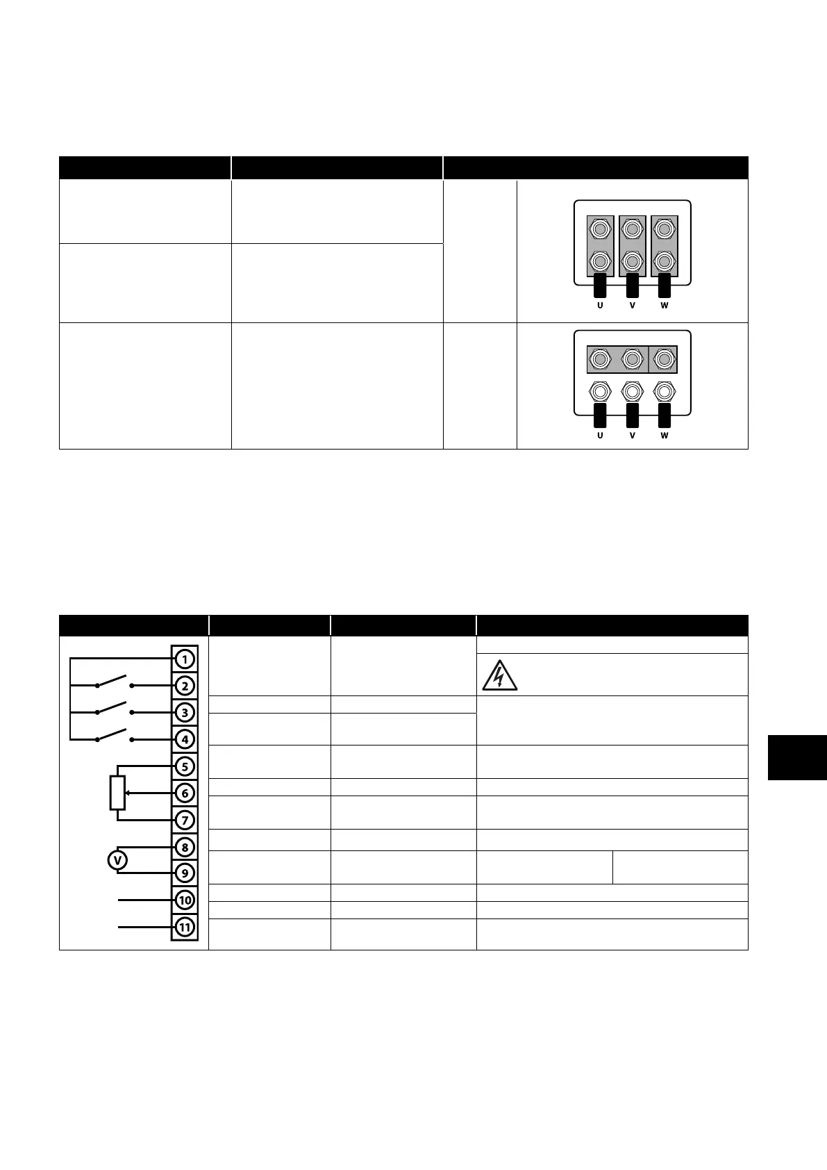
Incoming Supply Voltage Motor Nameplate Voltages Connection
230 230 / 400
Delta
∆
400 400 / 690
400 230 / 400
Star
⅄
4.6. Control Terminal Wiring
All analog signal cables should be suitably shielded. Twisted pair cables are recommended.
Power and Control Signal cables should be routed separately where possible, and must not be routed parallel to each other.
Signal levels of different voltages e.g. 24 Volt DC and 110 Volt AC, should not be routed in the same cable.
Maximum control terminal tightening torque is 0.5Nm.
Control Cable entry conductor size: 0.05 – 2.5mm2 / 30 – 12 AWG.
4.7. Control Terminal Connections
Default Connections Control Terminal Signal Description
1 +24Vdc User Output
+24Vdc user output, 100mA.
Do not connect an external voltage source to
this terminal.
2 Digital Input 1 Positive logic
“Logic 1” input voltage range: 8V … 30V DC
“Logic 0” input voltage range: 0V … 4V DC
3 Digital Input 2
4
Digital Input 3 /Analog
Input 2
Digital: 8 to 30V
Analog: 0 to 10V, 0 to 20mA or 4 to 20mA
5 +10V User Output +10V, 10mA, 1kΩ minimum
6
Analog Input 1 /
Digital Input 4
Analog: 0 to 10V, 0 to 20mA or 4 to 20mA
Digital: 8 to 30V
7 0V 0 Volt Common, internally connected to terminal 9
8
Analog Output /
Digital Output
Analog: 0 to 10V,
Digital: 0 to 24V
20mA maximum
9 0V 0 Volt Common, internally connected to terminal 7
10 Auxiliary Relay Common
11 Auxiliary Relay NO Contact
Contact 250Vac, 6A / 30Vdc, 5A
Intended to drive resistive load.
Power & Control Wiring
4
 Loading...
