Version 1.00 | Optidrive ODE-3 User Guide | 27www.invertekdrives.com
7. Analog and Digital Input Macro Configurations
7.1. Overview
Optidrive E3 uses a Macro approach to simplify the configuration of the Analog and Digital Inputs. There are two key parameters
which determine the input functions and drive behaviour:
P-12 Selects the main drive control source and determines how the output frequency of the drive is primarily controlled.
P-15 Assigns the Macro function to the analog and digital inputs.
Additional parameters can then be used to further adapt the settings, e.g.
P-16 Used to select the format of the analog signal to be connected to analog input 1, e.g. 0 – 10 Volt, 4 – 20mA.
P-30 Determines whether the drive should automatically start following a power on if the Enable Input is present.
P-31 When Keypad Mode is selected, determines at what output frequency / speed the drive should start following the enable
command, and also whether the keypad start key must be pressed or if the Enable input alone should start the drive.
P-47 Used to select the format of the analog signal to be connected to analog input 2, e.g. 0 – 10 Volt, 4 – 20mA.
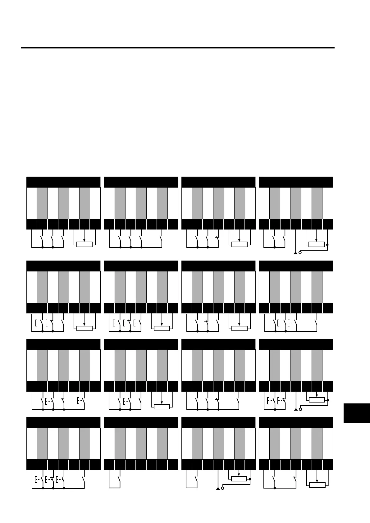
7.2. Example Connection Diagrams
The diagrams below provide an overview of the functions of each terminal macro function, and a simplified connection diagram for each.
Diagram 1 Diagram 2 Diagram 3 Diagram 4
+24V DC
DI 1
DI 2
DI 3
+10V DC
AI 1
0V / COM
+24V DC
DI 1
DI 2
DI 3
+10V DC
AI 1
0V / COM
+24V DC
DI 1
DI 2
DI 3
+10V DC
AI 1
0V / COM
+24V DC
DI 1
DI 2
DI 3
+10V DC
AI 1
0V / COM
1
2
3
4
5
6
7
1
2
3
4
5
6
7
1
2
3
4
5
6
7
1
2
3
4
5
6
7
Diagram 5 Diagram 6 Diagram 7 Diagram 8
+24V DC
DI 1
DI 2
DI 3
+10V DC
AI 1
0V / COM
+24V DC
DI 1
DI 2
DI 3
+10V DC
AI 1
0V / COM
+24V DC
DI 1
DI 2
DI 3
+10V DC
AI 1
0V / COM
+24V DC
DI 1
DI 2
DI 3
+10V DC
AI 1
0V / COM
1
2
3
4
5
6
7
1
2
3
4
5
6
7
1
2
3
4
5
6
7
1
2
3
4
5
6
7
Diagram 9 Diagram 10 Diagram 11 Diagram 12
+24V DC
DI 1
DI 2
DI 3
+10V DC
AI 1
0V / COM
+24V DC
DI 1
DI 2
DI 3
+10V DC
AI 1
0V / COM
+24V DC
DI 1
DI 2
DI 3
+10V DC
AI 1
0V / COM
+24V DC
DI 1
DI 2
DI 3
+10V DC
AI 1
0V / COM
1
2
3
4
5
6
7
1
2
3
4
5
6
7
1
2
3
4
5
6
7
1
2
3
4
5
6
7
Diagram 13 Diagram 14 Diagram 15 Diagram 16
+24V DC
DI 1
DI 2
DI 3
+10V DC
AI 1
0V / COM
+24V DC
DI 1
DI 2
DI 3
+10V DC
AI 1
0V / COM
+24V DC
DI 1
DI 2
DI 3
+10V DC
AI 1
0V / COM
+24V DC
DI 1
DI 2
DI 3
+10V DC
AI 1
0V / COM
1
2
3
4
5
6
7
1
2
3
4
5
6
7
1
2
3
4
5
6
7
1
2
3
4
5
6
7
Analog and Digital Input Macro Configurations
7
 Loading...
