30 | Optidrive ODE-3 User Guide | Version 1.00 www.invertekdrives.com
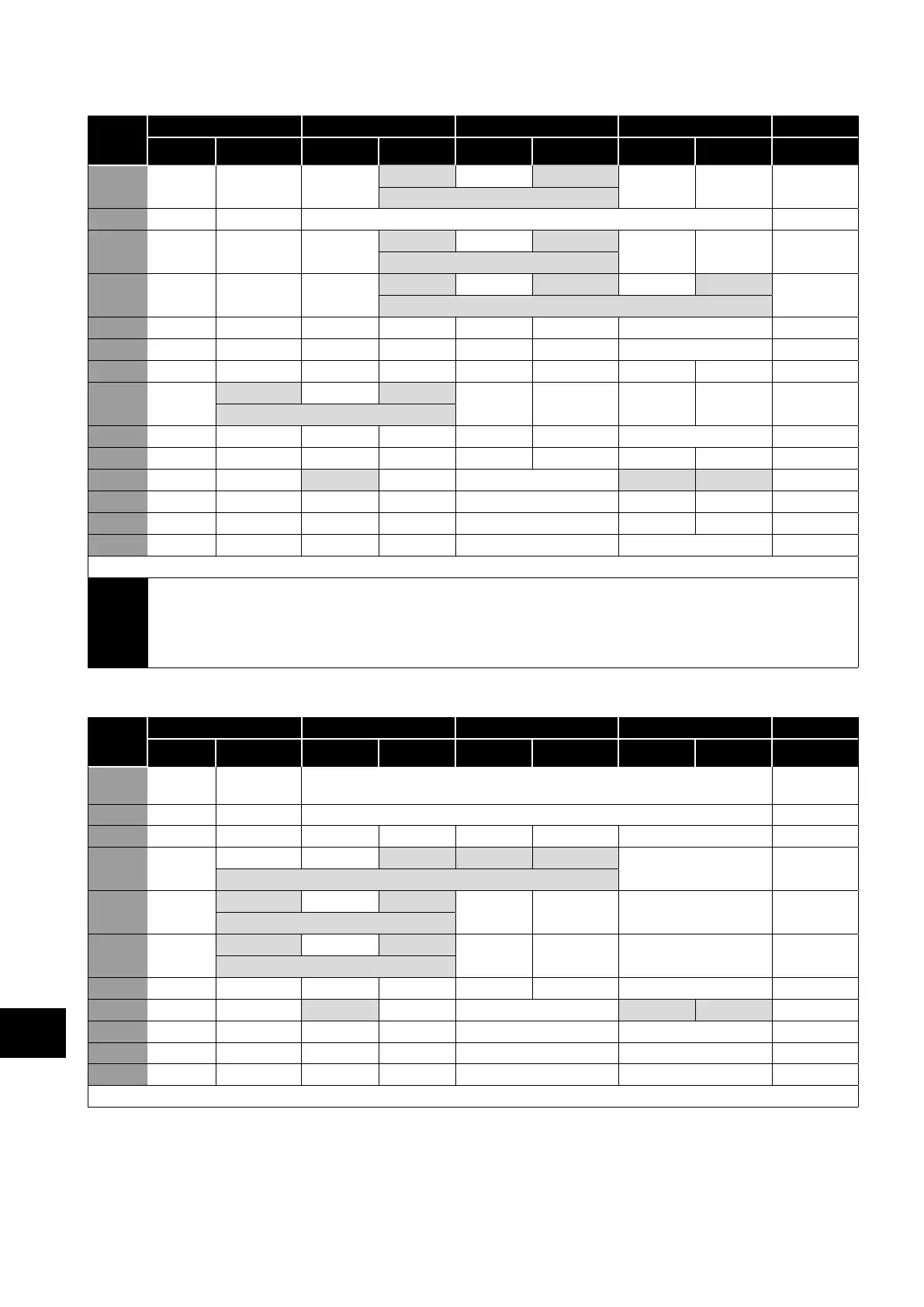
7.5. Macro Functions - Keypad Mode (P-12 = 1 or 2)
P-15
DI1 DI2 DI3 / AI2 DI4 / AI1 Diagram
0 1 0 1 0 1 0 1
0 STOP ENABLE -
INC SPD
-
DEC SPD FWD REV
8
^----------------START----------------^
1 STOP ENABLE PI Speed Reference 2
2 STOP ENABLE -
INC SPD
-
DEC SPD
KPD REF P-20 REF 8
^----------------START----------------^
3 STOP ENABLE -
INC SPD
E-TRIP OK -
DEC SPD
9
^-------------------------------START-------------------------------^
4 STOP ENABLE -
INC SPD
KPD REF AI1 REF AI1 10
5 STOP ENABLE
FWD REV
KPD REF AI1 REF AI1 1
6 STOP ENABLE
FWD REV
E-TRIP OK KPD REF P-20 REF 11
7 STOP RUN FWD STOP
RUN REV
E-TRIP OK KPD REF P-20 REF 11
^---------FAST STOP (P-24)---------^
8 STOP
RUN FWD
STOP
RUN REV
KPD REF AI1 REF AI1 1
14 STOP RUN -
INC SPD
E-TRIP OK -
DEC SPD
15 STOP RUN PR REF KPD REF Fire Mode P-23 P- 21 2
16 STOP RUN P-23 REF KPD REF Fire Mode
FWD REV
2
17 STOP RUN KPD REF P-23 REF Fire Mode
FWD REV
2
18 STOP RUN AI1 REF KPD REF Fire Mode AI1 1
9, 10, 11, 12, 13 = Behavior as per setting 0
NOTE
When P15=4 in keypad mode, DI2 &DI4 are edge triggered. Digital pot speed will be increased or
decreased once for each rising edge. The step of each speed change is defined by the absolute value of
Pre-set Speed 1 (P-20).
Speed change only happens during normal running condition (no stop command etc.). Digital pot will be
adjusted between minimum speed (P-02) and maximum speed (P-01).
7.6. Macro Functions - Fieldbus Control Mode (P-12 = 3, 4, 7, 8 or 9)
P-15
DI1 DI2 DI3 / AI2 DI4 / AI1 Diagram
0 1 0 1 0 1 0 1
0 STOP ENABLE FB REF (Fieldbus Speed Reference, Modbus RTU / CAN / Master-Slave
defined by P-12)
14
1 STOP ENABLE PI Speed Reference 15
3 STOP ENABLE FB REF P-20 REF E-TRIP OK Analog Input AI1 3
5 STOP ENABLE FB REF PR REF P-20 P- 21 Analog Input AI1 1
^----START (P-12 = 3 or 4 Only)----^
6 STOP ENABLE FB REF AI1 REF E-TRIP OK Analog Input AI1 3
^----START (P-12 = 3 or 4 Only)----^
7 STOP ENABLE FB REF KPD REF E-TRIP OK Analog Input AI1 3
^----START (P-12 = 3 or 4 Only)----^
14 STOP ENABLE - - E-TRIP OK Analog Input AI1 16
15 STOP ENABLE PR REF FB REF Fire Mode P-23 P- 21 2
16 STOP ENABLE P-23 REF FB REF Fire Mode Analog Input AI1 1
17 STOP ENABLE FB REF P-23 REF Fire Mode Analog Input AI1 1
18 STOP ENABLE AI1 REF FB REF Fire Mode Analog Input AI1 1
2, 4, 8, 9, 10, 11, 12, 13 = Behavior as per setting 0
7
Analog and Digital Input Macro Configurations
 Loading...
