32 | Optidrive ODE-3 User Guide | Version 1.00 www.invertekdrives.com
8. Modbus RTU Communications
8.1. Introduction
The Optidrive E3 can be connected to a Modbus RTU network via the RJ45 connector on the front of the drive.
8.2. Modbus RTU Specification
Protocol Modbus RTU
Error check CRC
Baud rate 9600bps, 19200bps, 38400bps, 57600bps, 115200bps (default)
Data format 1 start bit, 8 data bits, 1 stop bits, no parity
Physical signal RS 485 (2-wire)
User interface RJ45
Supported Function Codes 03 Read Multiple Holding Registers
06 Write Single Holding Register
16 Write Multiple Holding Registers (Supported for registers 1 – 4 only)
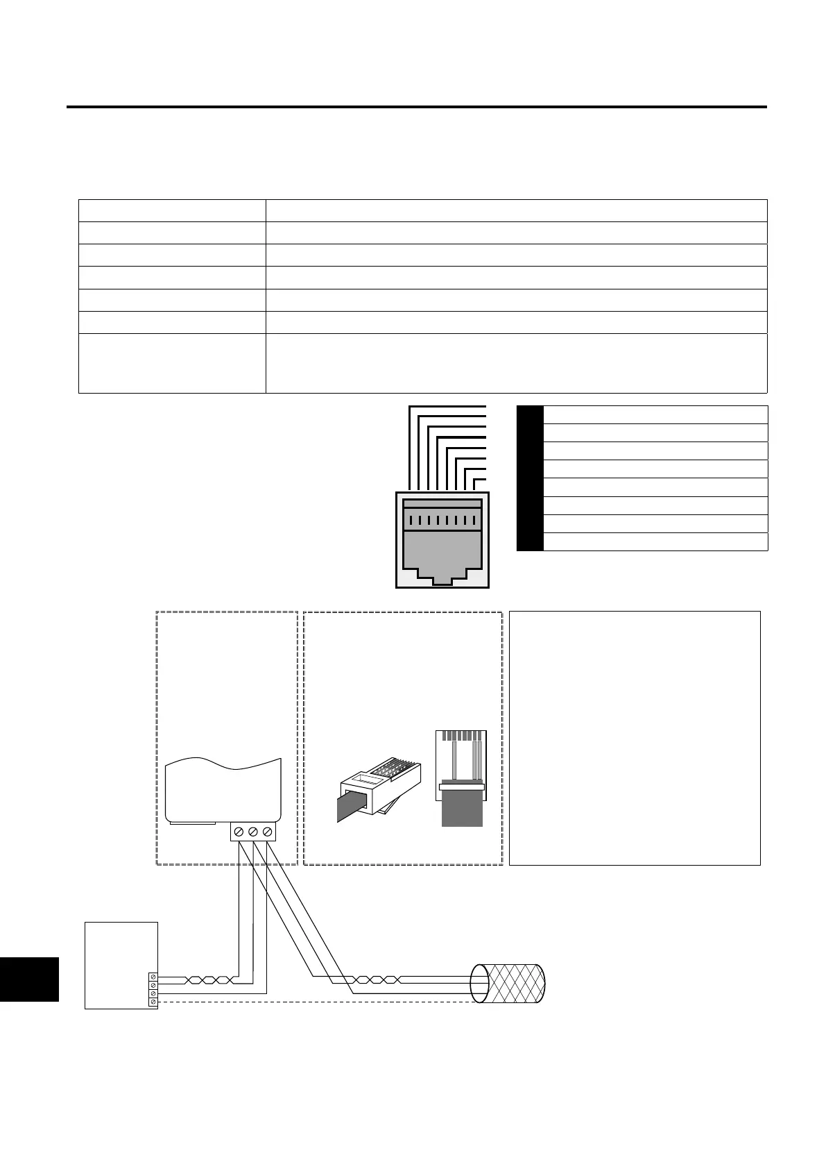
8.3. RJ45 Connector Configuration
For full MODBUS RTU register map information please
refer to your Invertek Drives Sales Partner. Local contacts
can be found by visiting our website:
www.invertekdrives.com
When using MODBUS control the Analog and Digital
Inputs can be configured as shown in section 7.6.
Macro Functions - Fieldbus Control Mode (P-12 = 3, 4,
7, 8 or 9).
1 CAN -
2 CAN +
3 0 Volts
4 -RS485 (PC)
5 +RS485 (PC)
6 +24 Volt
7 -RS485 (Modbus RTU)
8 +RS485 (Modbus RTU)
Warning: This is not an Ethernet connection.
Do not connect directly to an Ethernet port.
Modbus RTU
RS485 Controller
RS485+
RS485-
0 Volt / Common
Ground
NOTES
• Use 3 or 4 Conductor Twisted Pair Cable
•RS485+ and RS485- must be twisted pair
• Ensure the network taps for the drive
are kept as short as possible
• Using Option OPT-2-BNTSP-IN is
preferred
•Terminate the network cable shield at
the controller only. Do not terminate at
the drive!
•0 Volt common must be connected
across all devices and to reference 0 Volt
terminal at the controller
•Do not connect the 0V Common of the
network to power ground
RS485+
RS485-
0 Volt / Common
Shield
OPT-2-BNTSP-IN
OPT-2-BNTSP-IN
12 3
RS485+
0 Volt / Common
Connection to the
drive through the
option
OPT-2-BNTSP-IN
RS485-
Pin 3 –0 Volt / Common
Pin 7 – RS485- (Modbus RTU)
Pin 8 – RS485+ (Modbus RTU)
RJ45 connector pinout
Direct connection to the drive
through the built-in RJ45 port
1 2 3 4 5 6 7 8
1
2
3
4
5
6
7
8
Modbus RTU Communications
8
 Loading...
