Version 1.00 | Optidrive ODE-3 User Guide | 37www.invertekdrives.com
10. Troubleshooting
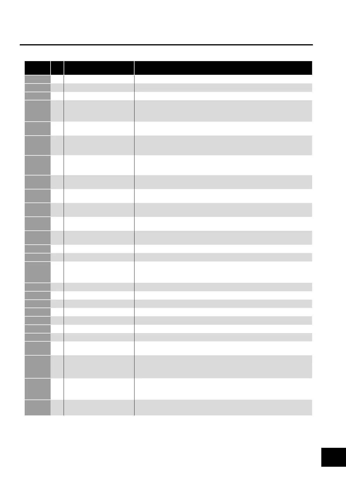
10.1. Fault Code Messages
Fault
Code
No. Description Suggested Remedy
l
00 No Fault Not required.
01 Brake channel over current Check external brake resistor condition and connection wiring.
L
02 Brake resistor overload The drive has tripped to prevent damage to the brake resistor.
03 Output Over Current Instantaneous Over current on the drive output. Excess load or shock load on the motor.
NOTE Following a trip, the drive cannot be immediately reset. A delay time is inbuilt,
which allows the power components of the drive time to recover to avoid damage.
.
04
Motor Thermal Overload (I2t)
The drive has tripped after delivering >100% of value in P-08 for a period of time to
prevent damage to the motor.
Vl
06 Over voltage on DC bus Check the supply voltage is within the allowed tolerance for the drive. If the fault occurs
on deceleration or stopping, increase the deceleration time in P-04 or install a suitable
brake resistor and activate the dynamic braking function with P-34.
Vl
07 Under voltage on DC bus The incoming supply voltage is too low. This trip occurs routinely when power is removed
from the drive. If it occurs during running, check the incoming power supply voltage and
all components in the power feed line to the drive.
08 Heatsink over temperature The drive is too hot. Check the ambient temperature around the drive is within the drive
specification. Ensure sufficient cooling air is free to circulate around the drive.
09 Under temperature Trip occurs when ambient temperature is less than -10°C. Temperature must be raised
over -10°C in order to start the drive.
10 Factory Default parameters
loaded
11 External trip E-trip requested on digital input 3. Normally closed contact has opened for some reason.
If motor thermistor is connected check if the motor is too hot.
C
12 Optibus comms loss Check communication link between drive and external devices. Make sure each drive in
the network has its unique address.
L
13 DC bus ripple too high Check incoming supply phases are all present and balanced.
L
14 Input phase loss trip Check incoming power supply phases are present and balanced.
15 Output Over Current Check for short circuits on the motor and connection cable.
NOTE Following a trip, the drive cannot be immediately reset. A delay time is inbuilt,
which allows the power components of the drive time to recover to avoid damage.
l
16 Faulty thermistor on heatsink
17 Internal memory fault (IO) Press the stop key. If the fault persists, consult you supplier.
18 4-20mA Signal Lost Check the analog input connection(s).
19 Internal memory fault (DSP) Press the stop key. If the fault persists, consult you supplier.
21 Motor PTC thermistor trip Connected motor thermistor over temperature, check wiring connections and motor.
22 Cooling Fan Fault (IP66 only) Check / replace the cooling fan.
23
Drive internal temperature too high
Drive ambient temperature too high, check adequate cooling air is provided.
26 Output Fault Indicates a fault on the output of the drive, such as one phase missing, motor phase
currents not balanced. Check the motor and connections.
41 Autotune Fault The motor parameters measured through the autotune are not correct.
Check the motor cable and connections for continuity.
Check all three phases of the motor are present and balanced.
C
50 Modbus comms loss fault Check the incoming Modbus RTU connection cable.
Check that at least one register is being polled cyclically within the timeout limit set in
P-36 Index 3.
C
51 CAN comms loss trip Check the incoming CAN connection cable.
Check that cyclic communications take place within the timeout limit set in P-36 Index 3.
NOTE Following an over current or overload trip (3, 4, 5, 15), the drive may not be reset until the reset time delay has elapsed to prevent
damage to the drive.
Troubleshooting
10
 Loading...
