Optidrive Compact-2 Engineering Guide Issue 07.docx
11.5. Response Times
<8ms From receipt of valid command
<8ms From receipt of valid command
<8ms, response, 60ms cycle
11.6. Motor Control Performance
11.6.1. V/F Mode
Speed Regulation: + / - 20% of motor slip with slip compensation enabled
11.6.2. Vector Mode
Static Speed Accuracy: + / - 0.033%
Speed Regulation 0 – 100% Load Range: + / - 1%
Torque Response: 1- 8ms
Torque Linearity (10 – 90% of motor rated speed, 20 – 100% load torque range): + / - 5%
11.7. Output Current Limit
11.7.1. Overload Operation
Optidrive Compact 2 provides the following maximum permissible overload current:-
150% Output current / 60 Seconds Maximum
175% Output current / 2.5 Seconds Maximum
In addition, maximum continuous output current available and maximum permissible overload time may be adjusted according to the following
PWM Switching Frequency Selected
Low Output Frequency
High Ambient Temperature
These functions are described more fully below.
11.7.2. Overview
Optidrive Compact2 features both hardware and software protection of the output stage to prevent damage. In addition, an Ixt system is used to
monitor motor overload condition and prevent damage to the motor due to operation for prolonged periods at high load.
I x t protection is software based, using the value for motor rated current programmed in P-08. An internal accumulator register is used to
estimate the point at which damage may occur to the motor, and operates as follows
Motor Current < P-08
The accumulator value reduces towards zero. The time required depends on the actual load current as explained further below.
Motor Current = 100% P-08
The accumulator value remains static.
Motor Current > 100% P-08 < 150% P-08
The accumulator value increases at a rate proportional to the overload level, e.g. (Motor Current / Rated current) – 100%. If the overload limit is
reached, the drive will trip, displaying it.trp. to protect the motor.
Motor Current > 150% P-08
For high current levels, the accumulator operates 16 times faster than for current levels below 150% of P-08.
Peak over current trip levels are shown in the table below.
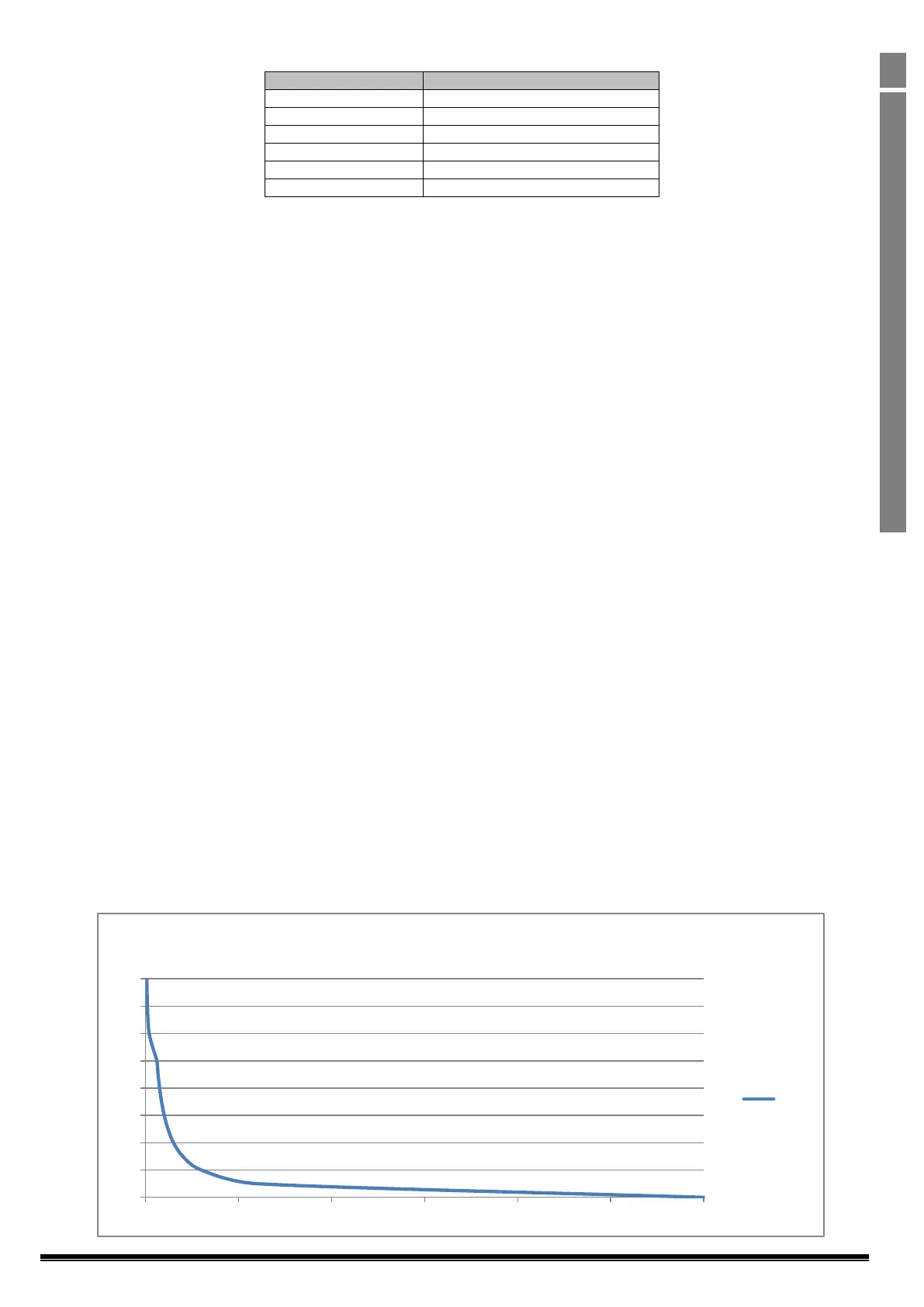
11.7.3. Example Operation
Maximum overload operation is 150% of motor rated current for 60 seconds. As this represents an overload of 50%, the accumulator trip level is
3000. This means that if the drive operates with 125% load current, the time can be calculated as 3000 / (125 – 100) = 120 Seconds.
Above 150% load, accumulation is 16 times faster, hence for 160% load current, the time is 3000 / 16 / (160 – 150) = 18.75 seconds
11.7.4. Overload Curve
100
110
120
130
140
150
160
170
180
0 500 1000 1500 2000 2500 3000
Time
Time