Optidrive Compact-2 Engineering Guide Issue 07.docx
Mechanical Information and Mounting
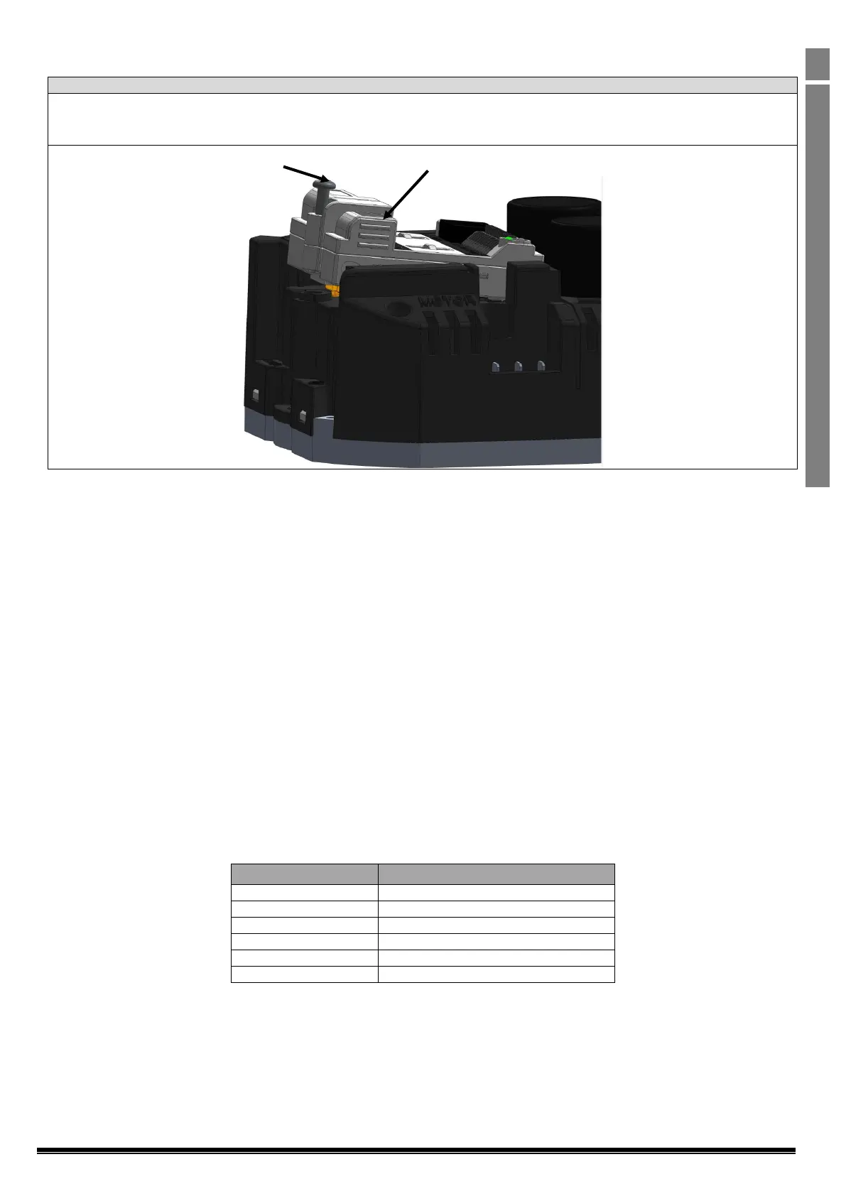
4.3. Removing/Changing the Control Module.
1. Fully unscrew the cross head screw.
2. Press finger grips and Lift the Control module from the screw side.
3. Rotate towards the control terminal side as shown.
4.4. Heatsink Capacity Calculation
Optidrive Compact 2 Units are designed to be mounted to a metallic, heat conducting surface in order to maintain the unit operating
temperature. Thermostrate or heatsink compound must be added to ensure optimal heat transfer and minimum thermal resistance.
In order to calculate the necessary heatsink requirement, the following formula can be used. Example values based on typical conditions are
given in the table below.
Determine the maximum ambient air temperature around the heatsink, T
AMB
Select the desired PWM operating frequency from the available options in Parameter P-17
From the table in section Error! Reference source not found. on page Error! Bookmark not defined. determine the maximum
permissible heatsink temperature, T
MAX
Determine the maximum allowed Temperature Rise
o T
RISE
= T
MAX
- T
AMB
Calculate the motor absorbed electrical power, P
MOT
, based on the motor rated voltage, current and efficiency
o P
MOT
= √3 * Rated Voltage * Rated Current * Power Factor * Efficiency
Calculate the losses in the drive, P
LOSS
, based on the required motor power
o P
LOSS
= P
MOT
* (1 - Drive Efficiency)
o Typical drive efficiency values are shown in the table below for each available effective switching frequency
Calculate the required heatsink maximum thermal resistance R
MAX
o R
MAX =
T
RISE /
P
LOSS
4.5. Maximum Permissible Heatsink Temperature
The maximum permissible heatsink temperature allowed for the Compact 2 drive is linked to the desired effective switching frequency selected
by parameter P-17. In order to maintain operation at a certain switching frequency, the heatsink temperature must be maintained below the
threshold level shown in the table below. If the temperature exceeds the threshold, the switching frequency will automatically reduce.
Auto reduce from 32kHz to 24kHz
Auto reduce from 24kHz to 16kHz
Auto reduce from 16kHz to 12kHz
Auto reduce from 12kHz to 8kHz
Over temperature trip if P-17 >= 8kHz
Over temperature trip if P-17 >= 8kHz
Note: Switching frequency may be automatically reduced under certain operating conditions, refer to section 11.950 Automatic Switching
Frequency Reduction for further information.
 Loading...


