Optidrive P2 Advanced User Guide Rev 2.00
Optidrive P2 Parameter Set Overview
1.4.3. Data Source Selection Parameters
Data Source selection parameters define the signal source for analog signals used within the drive, or example speed and torque setpoints.
These parameters can be linked to analog values within the drive.
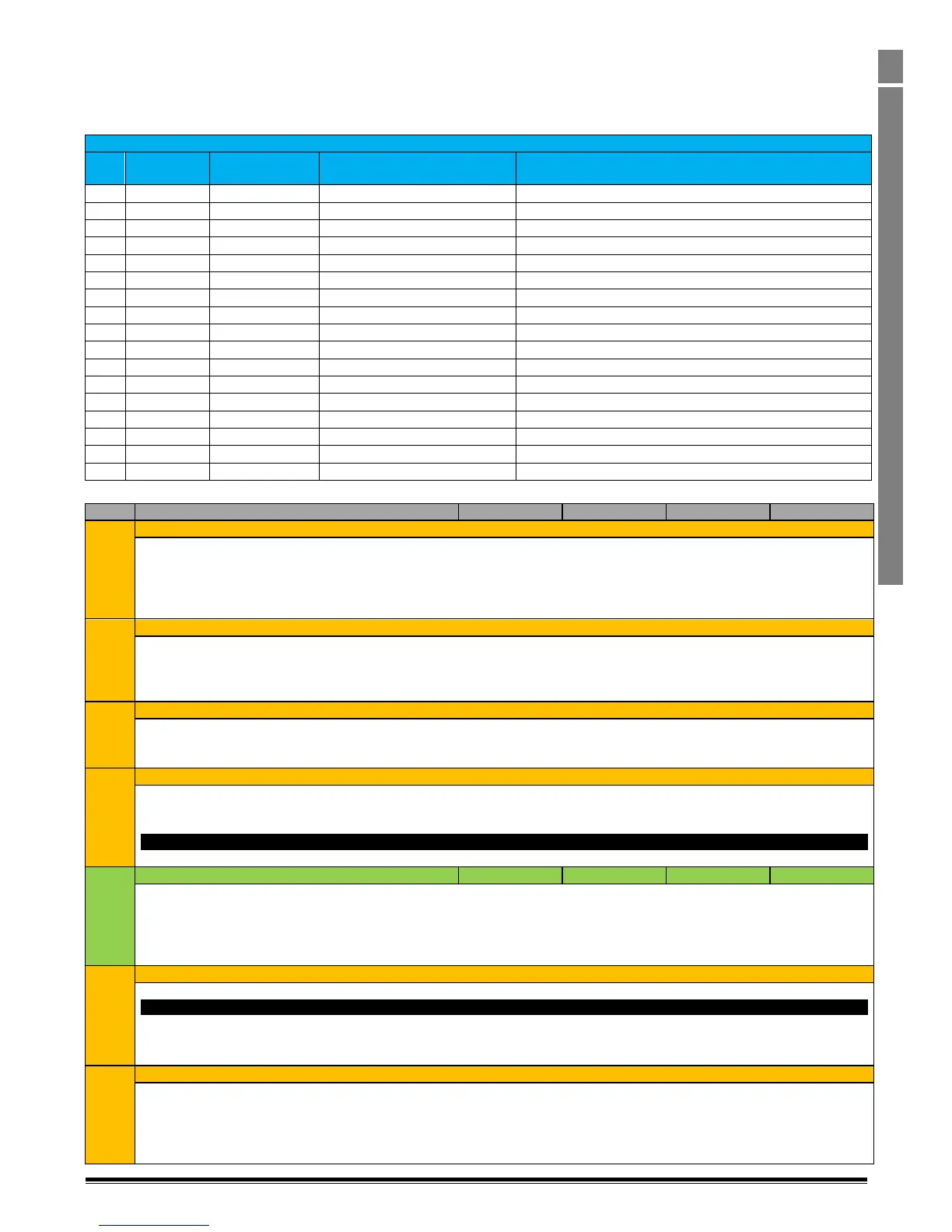
Parameters defined as Data Sources have the following range of possible settings:-
Programmable Logic Source Selection Options
Analog Input 1 Signal Level (P0-01)
Analog Input 2 Signal Level (P0-02)
Keypad Speed Reference (P0-06)
PID Controller Output (P0-10)
Master Speed Reference (Master / Slave Operation)
Fieldbus Speed Reference PDI2
User Defined Speed Reference
User Defined Speed Reference ( Function Block Program)
Pulse Frequency Input Reference
1.4.4. Parameter Group 9 Descriptions
Enable Input Logic Source
Defines the source of the Drive Enable function. This function must be provided by hardware, and is normally assigned to Digital Input
1, and allows a hardware enable signal to be utilised in situations where for example the Run Forward or Run Reverse commands are
applied from external sources, e.g. Fieldbus control signals or a Function Block Program.
Logic 1 : Drive operation is allowed
Logic 0 : Drive stops using deceleration ramp time selected by P9-26 & P9-27
Fast Stop Input Logic Source
Defines the Source of the Fast Stop Input. In response to a Fast Stop command, the drive stops using the deceleration time set in P2-
25.
Logic 1 : Drive operation is allowed
Logic 0 : Drive stops using the deceleration ramp time set in P2-25
Run Forward Input Logic Source
Defines the source of the Run Forward command.
Logic 1 : Drive runs the motor in the forward direction of rotation
Logic 0 : Drive stops using deceleration ramp time selected by P9-26 & P9-27
Run Reverse Input Logic Source
Defines the source of the Run Reverse command.
Logic 1 : Drive runs the motor in the reverse direction of rotation
Logic 0 : Drive stops using deceleration ramp time selected by P9-26 & P9-27
Note
When both the Run Forward and Run Reverse commands are applied to the drive simultaneously, the drive executes a Fast Stop.
Latch Function Enable Logic Source
0 : Disabled
1 : Enabled. Enables the latching function of the digital inputs.
The latching function allows momentary start signals to be used to start and stop the drive in either direction. In this case, the Enable
Input Source (P9-01) must be linked to a normally closed / open to stop control source. This control source must be Logic ‘1’ to allow
the drive to start. The drive will then respond to momentary or pulse start and stop signals as defined in parameters P9-03 and P9-04.
Reverse Input Logic Source
Defines the source of the Reverse command, which reverses the direction of motor rotation.
Note
The Reverse input only takes effect when the drive is operating in a Forward direction. Therefore
Applying Run Forward & Reverse inputs simultaneously = Motor Runs Reverse
Applying Run Reverse and Reverse inputs simultaneously = Motor Runs Reverse
Defines the source of the Reset command.
Logic 1 : Faults are reset on a rising edge of the Reset command.
Logic 0 : No effect