EasyManua.ls Logo

Invertek optidrive cp2 - P6-28 Value Selection

Invertek optidrive cp2
80 pages
Print Icon
To Next Page IconTo Next Page
To Previous Page IconTo Previous Page
Loading...
Optidrive P2 Advanced User Guide Rev 2.00
www.invertekdrives.com
29
Optidrive P2 Parameter Set Overview
1
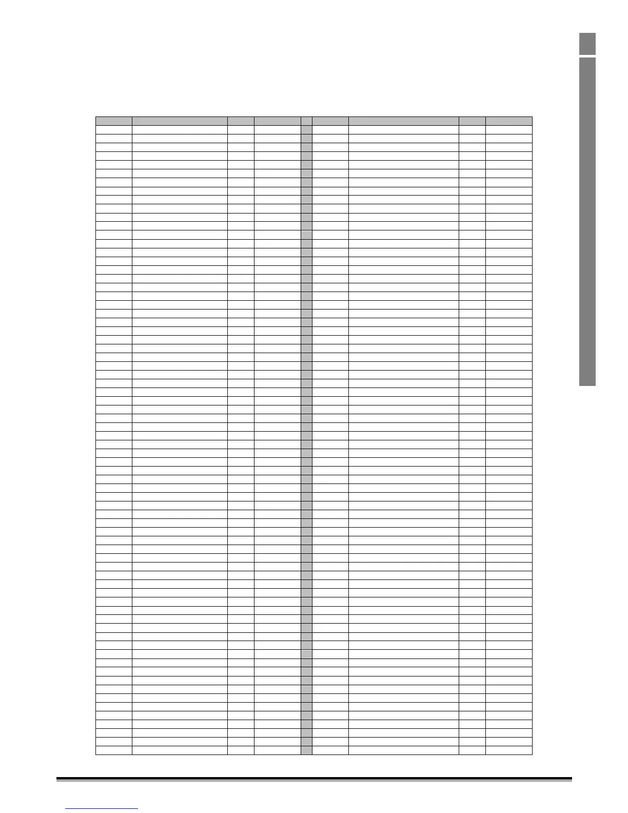
1.6. P6-28 Value Selection
Parameter P6-28 allows the user to select an internal register which can then be displayed in parameter P0-80.
To display any value from the list below, enter the corresponding index value in to P6-28.
E.g. setting P6-28 = 48 reads out the 24hour timer value in P0-80
Note that any of these variables can also be read out via the plug-in Fieldbus modules by setting PDO-3 or PDO-4 to P0-80 see section 1.3.5.
Address
Function Description
R/W
Remark
Address
Function Description
R/W
Remark
0
Off condition
R
Binary
81
Motor speed
R
Data
1
Digital input 1
R
Binary
82
Motor current
R
Data
2
Digital input 2
R
Binary
83
Motor torque
R
Data
3
Digital input 3
R
Binary
84
Motor power
R
Data
4
Digital input 4
R
Binary
85
PID speed reference
R
Data
5
Digital input 5
R
Binary
86
DC bus voltage
R
Data
6
Digital input 6
R
Binary
87
Drive temperature
R
Data
7
Digital input 7
R
Binary
88
AMB temperature
R
Data
8
Digital input 8
R
Binary
89
Scaling display value 1
R
Data
9
Analog output 1
R
Data
90
Scaling display value 2
R
Data
10
Analog output 2
R
Data
91
Reserved
R
11
Digital output 1
R
Binary
92
Reserved
R
12
Digital output 2
R
Binary
93
Extension IO input
R
Data
13
Digital output 3
R
Binary
94
Reserved
R
14
Digital output 4
R
Binary
95
Reserved
R
15
Digital output 5
R
Binary
96
Plug-In module ID
R
Data
16
On condition
R
Binary
97
Anybus module type ID
R
Data
17
User register 1 (RAM)
RW
Binary/Data
98
Anybus module error
R
Data
18
User register 2 (RAM)
RW
Binary/Data
99
Anybus status
R
Data
19
User register 3 (RAM)
RW
Binary/Data
100
Reserved
R
Data
20
User register 4 (RAM)
RW
Binary/Data
101
Scope channel 1 data
R
Data
21
User register 5 (RAM)
RW
Binary/Data
102
Scope channel 2 data
R
Data
22
User register 6 (RAM)
RW
Binary/Data
103
Scope channel 3 data
R
Data
23
User register 7 (RAM)
RW
Binary/Data
104
Scope channel 4 data
R
Data
24
User register 8 (RAM)
RW
Binary/Data
105
OLED language index
R
Data
25
User register 9 (RAM)
RW
Binary/Data
106
OLED display version
R
Data
26
User register 10 (RAM)
RW
Binary/Data
107
Reserved
R
27
User register 11 (RAM)
RW
Binary/Data
108
Drive Rating ID
R
Data
28
User register 12 (RAM)
RW
Binary/Data
Reserved
R
29
User register 13 (RAM)
RW
Binary/Data
119
FS8 Stir Fan Speed
R
Data
30
User register 14 (RAM)
RW
Binary/Data
31
User register 15 (RAM)
RW
Binary/Data
123
Function Block Program Cycle Time
R
Data
32
User analog output 1
RW
Data
124
Function Block Program ID
R
Data
33
User analog output 2
RW
Data
Reserved
R
34
Reserved
RW
Data
130
kWh meter (user resettable)
R
Data
35
Reserved
RW
Data
131
MWh meter (user resettable)
R
Data
36
User relay/digital output 1
RW
Binary
132
kWh meter (fixed)
R
Data
37
User relay/digital output 2
RW
Binary
133
MWh meter (fixed)
R
Data
38
User relay/digital output 3
RW
Binary
134
Total run hour
R
Data
39
User relay/digital output 4
RW
Binary
135
Total run minutes and seconds
R
Data
40
User relay/digital output 5
RW
Binary
136
Run hour since last enable
R
Data
41
User scaling value
RW
Data
137
Run min/sec since last enable
R
Data
42
User scaling decimal
RW
Data
Reserved
R
43
User speed reference
RW
Data
143
Real time clock second
R
Data
44
User torque reference
RW
Data
144
Real time clock minute
R
Data
45
User/fieldbus ramp reference
RW
Data
145
Real time clock hour
R
Data
46
Scope index 1/2
RW
Data
146
Real time clock weekday
R
Data
47
Scope index 3/4
RW
Data
147
Real time clock day
R
Data
48
24hour timer clock (hh:mm)
RW
Data
148
Real time clock month
R
Data
49
User display control register
RW
Data
149
Real time clock year
R
Data
50
User display value register
RW
Data
Reserved
R
Reserved
RW
185
User register 16 (RAM)
RW
Binary/Data
61
Analog input 1 (Q12)
R
Data
186
User register 17 (RAM)
RW
Binary/Data
62
Analog input 1 (%)
R
Data
187
User register 18 (RAM)
RW
Binary/Data
63
Analog input 2 (Q12)
R
Data
188
User register 19 (RAM)
RW
Binary/Data
64
Analog input 2 (%)
R
Data
189
User register 20 (RAM)
RW
Binary/Data
65
Digital input status (1~5)
R
Data
190
User register21 (RAM)
RW
Binary/Data
66
Speed reference
R
Data
191
User register 22 (RAM)
RW
Binary/Data
67
Digital speed pod
R
Data
192
User register 23 (RAM)
RW
Binary/Data
68
Field bus speed reference
R
Data
193
User register 24 (RAM)
RW
Binary/Data
69
Master speed reference
R
Data
194
User register 25 (RAM)
RW
Binary/Data
70
Slave speed reference
R
Data
195
User register 26 (RAM)
RW
Binary/Data
71
Frequency speed reference
R
Data
196
User register 27 (RAM)
RW
Binary/Data
72
Torque reference (Q12)
R
Data
197
User register 28 (RAM)
RW
Binary/Data
73
Torque reference (%)
R
Data
198
User register 29 (RAM)
RW
Binary/Data
74
Master torque reference
R
Data
199
User register 30 (RAM)
RW
Binary/Data
75
Fieldbus torque reference
R
Data
200
User register 31 (RAM)
RW
Binary/Data
76
PID user reference
R
Data
77
PID user feedback
R
Data
78
PID reference
R
Data
79
PID feedback
R
Data
80
PID output
R
Data