Optidrive P2 Advanced User Guide Rev 2.00
Optidrive P2 Parameter Set Overview
1.4. Parameter Group 9 – Programmable Logic Functions
Parameter Group 9 is intended to allow the user complete flexibility to control the behaviour of the drive in more complex applications which
require specialised parameter settings to accomplish. The parameters contained within this group should be used carefully, and the user
should ensure they are fully familiar with the operation of the drive and its control functions prior to making any adjustment to parameters
contained within this group.
1.4.1. Parameter Group 9 Function Overview
Parameter Group 9 allows advanced programming of the drive, including user defined functions for the digital and analog inputs of the drive
and control of the speed reference source.
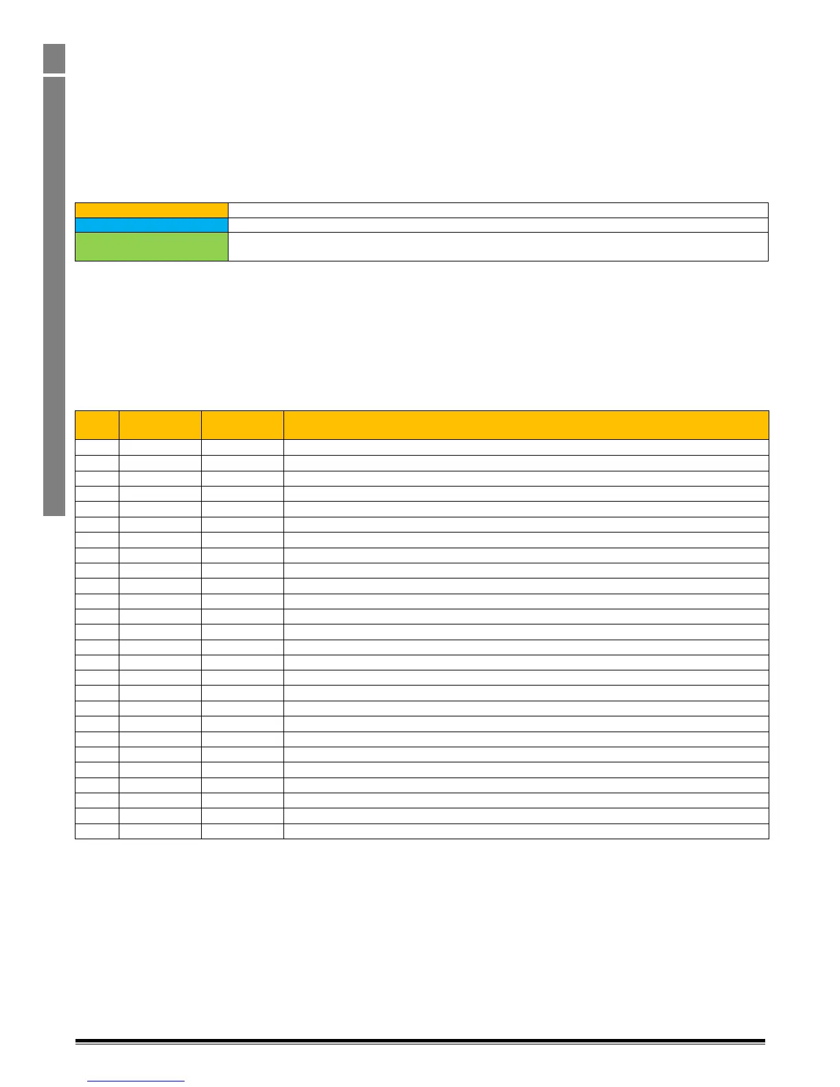
Group 9 Consists of three types of parameters
These can be used to select the source for programmable Digital signals internally within the drive
These can be used to select the source for programmable Analog signal sources within the drive
Function Enable Parameters
These are used to select whether drive functions are controlled by their usual parameter selection, or have
user defined behaviour (e.g. controlled by a Function Block Program within the drive written by the user).
The following rules apply to parameter Group 9.
Parameters P9-01 to P9-32 inclusive may only be changed when P1-13 = 0
When the value of P1-13 is changed, all previous settings in Parameter Group 9 will be cleared, and new settings entered based on
the P1-13 selection.
1.4.2. Logic Source Selection Parameters
Logic Source Selection parameters allow the user to directly define the source for a control function within the drive. These parameters can
only be linked to digital values, which either enable or disable the function depending on their state.
Parameters defined as logic sources have the following range of possible settings:-
Function permanently disabled, or where allowed, linked to the status of the STO inputs
Function linked to Digital Input 1 Status
Function linked to Digital Input 2 Status
Function linked to Digital Input 3 Status
Function linked to Digital Input 4 (Analog Input 1) Status
Function linked to Digital Input 5 (Analog input 2) Status
Function linked to Digital Input 6 Status (Requires Extended I/O option)
Function linked to Digital Input 7 Status (Requires Extended I/O option)
Function linked to Digital Input 8 Status (Requires Extended I/O option)
Function linked to Analog Output 1 Status
Function linked to Analog Output 2 Status
Function linked to Relay Output 1 Status
Function linked to Relay Output 2 Status
Function linked to Relay Output 3 Status (Requires Extended I/O or Cascade Option)
Function linked to Relay Output 4 Status (Requires Cascade Option)
Function linked to Relay Output 5 Status (Requires Cascade Option)
Function permanently enabled
Function linked to User Register 1 (Function Block Program)
Function linked to User Register 2 (Function Block Program)
Function linked to User Register 3 (Function Block Program)
Function linked to User Register 4 (Function Block Program)
Function linked to User Register 5 (Function Block Program)
Function linked to User Register 6 (Function Block Program)
Function linked to User Register 7 (Function Block Program)
Function linked to User Register 8 (Function Block Program)
Function linked to User Register 9 (Function Block Program)